You are using an out of date browser. It may not display this or other websites correctly.
You should upgrade or use an alternative browser.
You should upgrade or use an alternative browser.
Heater Meter V4.2.3 build questions
- Thread starter RalphTrimble
- Start date
John Bostwick
TVWBB Wizard
I was just going to say I liked Ralph case idea. But, I will hold off on that. And I will just say that I do like the idea of a case with the probe Jacks one one piece like the one Ralph showed pictures of even if using screws to hold the back on, if needed.It must have been pretty challenging designing your case from the 3d files I was sending you all weekend as I redesigned it for you. Way to show some integrity by passing it off as your own.
I was just going to say I liked Ralph case idea. But, I will hold off on that. And I will just say that I do like the idea of a case with the probe Jacks one one piece like the one Ralph showed pictures of even if using screws to hold the back on, if needed.
The push fit and single probe jack wall were not part of my design. It's the overall design, new LCD bezel, measurements, etc. that is a bit frustrating to see presented in a "new design", when I sat in front of a computer for several hours preparing files for this person. Imagine if I took Bryan's EAGLE files that he sent me, moved a piece or two, and then posted it as my new heatermeter design. It's just something that you don't do.
RalphTrimble
TVWBB Diamond Member
It must have been pretty challenging designing your case from the 3d files I was sending you all weekend as I redesigned it for you. Way to show some integrity by passing it off as your own.
That is kinda insulting Tom, I assure you I started out with rectangle and circles and designed every bit of my case using a caliper referencing the HM board, I didn't use your case or design as a reference at all. If there are similarities it is only because we are both building a box around the same hardware, my one piece shell is actually quite different from your split design in reality. If you need to see my 3D files including sketches and my box full of rough design rejects I've got them to show...
I had a rough design printed on Friday night of my case and interrupted my progress to print your case and give you feedback ASAP, when things didn't fit with yours I resumed work on my project (as I always intended to). I know you are designing your case for the upcoming 4.2 release anyway, so I don't understand you saying it was all done for "me"? Again, I am pretty insulted that you would accuse me of passing off your design as my own, you only sent me STL's of your design and I don't even have software to re-engineer them into editable 3D models. Did I design a case for my HM prototybe HM board, YES... Did I take your design and pass it off as my own? Hell no, I wouldn't do that....
RalphTrimble
TVWBB Diamond Member
The push fit and single probe jack wall were not part of my design. It's the overall design, new LCD bezel, measurements, etc. that is a bit frustrating to see presented in a "new design", when I sat in front of a computer for several hours preparing files for this person. Imagine if I took Bryan's EAGLE files that he sent me, moved a piece or two, and then posted it as my new heatermeter design. It's just something that you don't do.
Perhaps you are forgetting that I actually built the prototype HM board and have it here in hand to measure and design around, which is exactly what I did. You continue to insinuate that I took your file and edited it to be "my own", which I did NOT do. I spent the hours this weekend and did it myself just as you did, mainly because I like a challenge... I didn't start from your file and there was no copy/paste or measurement reference to your 3D design or printed part at all. The reason why the LCD is inset on my unit is because that is the position it is in by Bryan's design, I just worked around it. As a matter of fact, I think your design has the LCD inset quite a bit to set the button back enough to be flush while my design has the LCD only 1mm from the face and uses the custom button nub that is allowed to protrude through the face... so they're... different, in many ways, even ways you seem to think they are similar....
RalphTrimble
TVWBB Diamond Member
The timing seems a little coincidental. And you're correct, I was designing for the upcoming 4.24 board. But I was simultaneously making a design especially for you and Bryan who have 4.23 boards which are slightly different.
I understand your reaction, to a point, Tom. You do great work and I have appreciated your cases very much through the HM versions. If timing seems suspect, consider this.... I've been waiting to build this prototype HM for a while now, invested the money and time into the hardware and build, and testing, including ideas I have contributed to the design which I am extremely grateful to see implemented. I completed most of the build early this week and got the last bits and pieces to have a working unit on Wed, tested it on Thursday without a case and immediately started designing my own case then because I have always wanted to take a stab at it and had been pondering my design ideas for a good part of the week as I built the unit. With a prototype board in hand, without a case, it just seemed like the time to dig in and do it. This thread is pretty much documents all that, so the timing is based on that.. If you hadn't been so on the job working on your design I would have posted mine before you even took a crack at it...
RalphTrimble
TVWBB Diamond Member
If it's merely a coincidence then I apologize. You just have to understand how it looks from my vantage point.
No apology required, I get it... Please just know that I didn't plagiarize your design and am not trying to step on your toes either... You have given very much to the forum, and to me directly in assistance with my 3D printer project... and I thank you for that.
Mark Workman
New member
I have question/suggestion about the 4.2.x board layout. Forgive me as I make an assumption too... In 4.2.x, the RJ-45 connector is also used for fan/servo connections (My assumption is that it is just like the 4.1.4 layout). Thus, the 4.2.x design uses only 4 of the 8 available pins in the RJ-45 connector. Will this change in 4.2.x?
Here is what I am thinking. Why leave pins unused? Why not double them up. In other words, have two ground pins, two +5v pins, two fan (+12v) pins and two servo pins? Doing this will make better use of the wires in the connector and cabling. Thus, reducing the current draw on any individual wire in the cable. Allowing greater range (less voltage drop)... more redundancy (less chance a bad cable or connector will give you trouble), and it may help dampen noise coming back from the fan or servo.
It is just a thought.
Bryan Mayland
TVWBB Hall of Fame
Because you can do whatever you want with them. If you want to double up, then go for it. Ralph wants to run probe signals down them, go for it. Whatever you want to connect down on the other end is your business. A 4 wire connection can also be run from an RJ11 cord. I don't see any point in redundant connections because it limits the functionality to only one use.
RalphTrimble
TVWBB Diamond Member
I agree with Bryan, if you want the pins doubled up for whatever reason you can easily do that on your own by solder bridges or using wires at the solder joints on the jack, or you can connect the probes if you prefer that. The next stop for me is throwing 3.3v down one of the extra wires to power a remote thermocouple circuit as an experiment to see if it's possible to run it over the CAT5 cable like the probes...
RalphTrimble
TVWBB Diamond Member
I had been using my HM4.0 for a couple of days while I was working on the case for my HMv4.2.3 prototype, tonight I went back to the HMv4.2.3 and boy did I notice the difference (again), the probes read so smooth on the new board, it's awesome...
So far I haven't found a problem with the 4.2.3 board using thermistor probes and the long CAT5 cable, and the thermocouple seemed to work well, read clean when I ran it on the bench, though I haven't done any cooks with it yet....
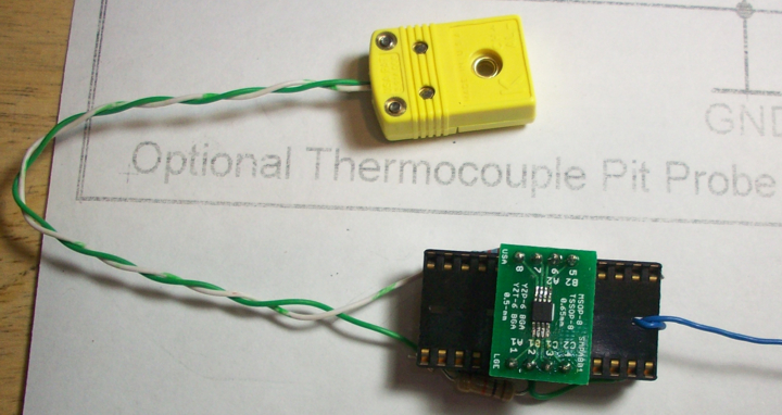
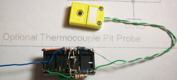
I built up the thermocouple circuit in a stand alone package tonight and my next step is to do some test runs of the pit with the thermocouple, then run the pit from the thermocouple over the CAT5 cable using the thermocouple amp built into the HM board, then run the pit from the thermocouple with the stand alone amp out at the grill side (with the built in amp isolated). I'm hoping that goes surprisingly well like everything else on the HMv4.2.3 board!
Here are a couple pictures of the standalone test thermocouple amp I built:
So far I haven't found a problem with the 4.2.3 board using thermistor probes and the long CAT5 cable, and the thermocouple seemed to work well, read clean when I ran it on the bench, though I haven't done any cooks with it yet....
I built up the thermocouple circuit in a stand alone package tonight and my next step is to do some test runs of the pit with the thermocouple, then run the pit from the thermocouple over the CAT5 cable using the thermocouple amp built into the HM board, then run the pit from the thermocouple with the stand alone amp out at the grill side (with the built in amp isolated). I'm hoping that goes surprisingly well like everything else on the HMv4.2.3 board!
Here are a couple pictures of the standalone test thermocouple amp I built:
Last edited:
RalphTrimble
TVWBB Diamond Member
I made the first step into testing the thermocouple over the CAT5 cable last night. I made an adapter that had a female thermocouple plug on one end and two probe jacks on the other, wired the Thermocoule (+) to one jack on my roto damper and (-) to another then plugged in the adapter. Running over the long CAT5 cable the thermocouple showed quite an offset, reading up about 30 degrees from where it should be, however, it didn't seem overly noisy or anything. The thermocouple tracks pretty smoothly on the graph, it's not real jittery or anything like I used to get when my thermistor probes were picking up interference... I didn't do a test cook, I just set the thermocouple along side a Maverick 73 probe inside my unlit grill over night to see how it would do. I have no idea how the temp will track in a real cook over a wide range of temps, but at room temp I was able to use the offest to get the thermocouple to read where it should be. I will try to light the pit this afternoon and see how it tracks compared to the M73 over a lit fire.....
Next stop is to change over my wiring to send 3.3v down one probe jack to power my stand alone thermocouple amp out at the grill side, and use another probe jack to send the output of that amp back to the heater meter, where I will disconnect the onboard thermocouple amp from the circuit at the 100k resistor and inject the signal from the remote amp and see how the thermocouple registers with that....
Next stop is to change over my wiring to send 3.3v down one probe jack to power my stand alone thermocouple amp out at the grill side, and use another probe jack to send the output of that amp back to the heater meter, where I will disconnect the onboard thermocouple amp from the circuit at the 100k resistor and inject the signal from the remote amp and see how the thermocouple registers with that....
Bryan Mayland
TVWBB Hall of Fame
Yeah the problem is that you can't transfer thermocouple wires to copper wires and then expect the reading to be right on the far end. It's the basics of how thermocouples work in that they're just two pieces of wire made from different materials and where the material changes there's a current flow that's related to the temperature of the junction. That current then has to be calibrated against the another junction of a known temperature which you've got 100ft away where the amp can't see it. The value you get is going to vary wildly depending on the temperature inside the HeaterMeter vs the temperature at the rotodamper. Of course, if you wire it with thermocouple wire all the way with no copper in between you'll be good to go but that's not exactly practical for your cable.
When you switch for putting the thermocouple on the far side, you probably want to keep the 100kohm/0.1uF filter on the HeaterMeter then just have no filtering on the output on the far end. There will be very little noise for the filter to remove on the far side but there will be plenty coming down the wire, so remove it at the end.
When you switch for putting the thermocouple on the far side, you probably want to keep the 100kohm/0.1uF filter on the HeaterMeter then just have no filtering on the output on the far end. There will be very little noise for the filter to remove on the far side but there will be plenty coming down the wire, so remove it at the end.
RalphTrimble
TVWBB Diamond Member
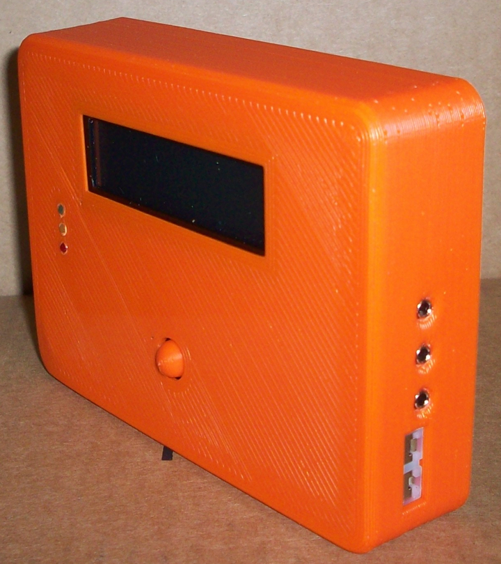
I also made some major strides with my HMv4.2.3 case last night. I printed V3 of my design and it came out great! I pondered the press-n-fit concept a bit and found no real solution to make sure the back fit solid from print to print, and over time etc without at least two screws... then while thinking about how I have always wanted an easy access door for the SD Card it came to me that perhaps a slide-in back would be even better than a press-n-fit. So I set out to design a slide-in removable back and it worked out awesome! The back fits in snug and solid yet removes/opens very easily to access the SD Card and electronics, I think this one is a winner, I may call it done at this point...
Here are a couple pictures of my V3 design:
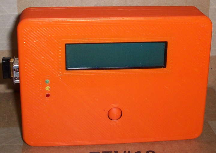
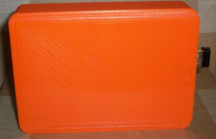
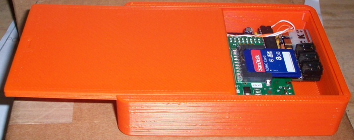
Since I do so much messing around with my HM the sliding removable back is gonna be a big convenience for me. Just slide it open a bit to remove the SD Card, or slide it all the way out and the HM boards flip right out in your hands, super easy....
The only other thing I might do with the case is possibly make an opening for the HDMI output and audio on the rPi, this way you could slide the back open, swap out the SD Card and use it as a media center PC or whatever else you may want to use your rPi for....
Here is a link to the STL's for the V3 case...
I sliced this one coarse as well, first layer at .4 and the rest at .5, using the E3D .6 hotend. The button needs to be sliced finer or it will end up kinda pointy, I sliced the button pictured at .2 for all layers. The case printed up really nice even when sliced coarse, but I'm sure it will work out great if sliced finer, depends on the size of your hotend nozzle and how long you want to wait for the print....
Here are a couple pictures of my V3 design:
Since I do so much messing around with my HM the sliding removable back is gonna be a big convenience for me. Just slide it open a bit to remove the SD Card, or slide it all the way out and the HM boards flip right out in your hands, super easy....
The only other thing I might do with the case is possibly make an opening for the HDMI output and audio on the rPi, this way you could slide the back open, swap out the SD Card and use it as a media center PC or whatever else you may want to use your rPi for....
Here is a link to the STL's for the V3 case...
I sliced this one coarse as well, first layer at .4 and the rest at .5, using the E3D .6 hotend. The button needs to be sliced finer or it will end up kinda pointy, I sliced the button pictured at .2 for all layers. The case printed up really nice even when sliced coarse, but I'm sure it will work out great if sliced finer, depends on the size of your hotend nozzle and how long you want to wait for the print....
Last edited:
RalphTrimble
TVWBB Diamond Member
Yeah the problem is that you can't transfer thermocouple wires to copper wires and then expect the reading to be right on the far end. It's the basics of how thermocouples work in that they're just two pieces of wire made from different materials and where the material changes there's a current flow that's related to the temperature of the junction. That current then has to be calibrated against the another junction of a known temperature which you've got 100ft away where the amp can't see it. The value you get is going to vary wildly depending on the temperature inside the HeaterMeter vs the temperature at the rotodamper. Of course, if you wire it with thermocouple wire all the way with no copper in between you'll be good to go but that's not exactly practical for your cable.
When you switch for putting the thermocouple on the far side, you probably want to keep the 100kohm/0.1uF filter on the HeaterMeter then just have no filtering on the output on the far end. There will be very little noise for the filter to remove on the far side but there will be plenty coming down the wire, so remove it at the end.
OK, no copper... So... I assume the no copper rule would apply to the wire between the thermcouple and the amp, and not between the amp and the atmega. So it would seem putting the amp out at the damper might be a way around that problem. I have some thermocouple connector panel jacks but will need a short piece of wire to go between the panel jack and the amp circuit, do you think a couple inches of copper wire will cause a problem? If so, is there another kind of wire that I can use instead of copper that wont cause a problem... I guess I will have to research thermocouple wire a bit...
On the HM end I was planning on lifting one end of the 100K resistor that is in series with the probe lead (the end that is not connected to the ATMega) and insert the output from the remote amp there. I know that is the resistor in the RC filter, but I didn't look to see if lifting that end of the resistor will take the filter capacitor out of the circuit, I will have to dig into that a bit and make sure, and I will add another cap to the circuit if it ends up being left out....
Bryan Mayland
TVWBB Hall of Fame
Ah now I see what you're saying about the 100k cap. Yeah you've got it right, just feed the new connection into the 100k resistor with the end that connected to the old amp.
I've seen things say that you're supposed to use thermocouple wire to wire panel jacks. I think the only thing is that the point where it changes from chromel/alumel to copper has to be the exact same temperature as the amp is. In the HeaterMeter this is done by the close proximity of the amp to the connector, and being on a large chunk of shared thermal mass.
I've seen things say that you're supposed to use thermocouple wire to wire panel jacks. I think the only thing is that the point where it changes from chromel/alumel to copper has to be the exact same temperature as the amp is. In the HeaterMeter this is done by the close proximity of the amp to the connector, and being on a large chunk of shared thermal mass.
RalphTrimble
TVWBB Diamond Member
I've seen things say that you're supposed to use thermocouple wire to wire panel jacks. I think the only thing is that the point where it changes from chromel/alumel to copper has to be the exact same temperature as the amp is. In the HeaterMeter this is done by the close proximity of the amp to the connector, and being on a large chunk of shared thermal mass.
OK, if this works out my ultimate plan is to build a small box that will mate with the open wiring cavity in the roto damper to house the thermcouple amp and thermcouple panel jack, so the panal jack and amp will be right on top of each other and should be the same temp. I know my test circuit is crude, but if it works reasonably well I may have a circuit board fab'd that would have the thermocouple circuit, a thermocouple panel jack, regular probes jacks, a header to connect the servo, a jack to connect the blower and the CAT5 jack built in. This would be an all-in-one solution that would be used in the roto damper to provide thermocouple support and all I/O so wiring would be easier...