Heater Meter V4.2.3 build questions


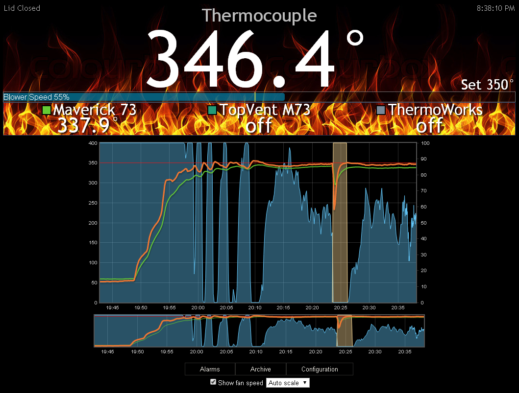
Here is a screen shot from my first burn with the Thermocouple as the pit probe, running over the long CAT5 cable, using the HM internal thermocouple amp. I have the thermocouple set at -25 offset cause the thermocouple reading jumped roughly 25 degrees when I moved it to the end of the long Cat5 cable. It is clipped to a Maverick73 probe as a reference and they are both inserted into the top vent of my Fauxmado...
Cat5Thermocouple.jpg


From the first few puffs of the damper it seems apparent that the HM is not used to the very fast response of the thermocouple (or should I say my PID settings). You can see the same fluctuations in the Maverick73 probe, just accentuated on the thermocouple. So far, with the offset, the thermocouple seems to track pretty accurately with the Maverick73 probe, perhaps a 30 or so offset would be more appropriate but the separation between the readings is good for examination purpose... Considering what Bryan has said about how thermocouples work, the temp of the junction and amp chip and all, I assume this offset might vary depending on the outdoor temp... so I guess will experiment with a pair of probes for a while until I get an idea how this works in different weather conditions.

All in all I am really happy how it is going so far, after I get a few cooks under my belt with this setup I will move the amp out to the damper and see how that works out....
 
I could see that causing all sorts of problems if the sun heats the rotodamper or something and causes your offset to change dramatically in the middle of a cook. It's going to be much better with the amp in the rotodamper.

When you made your slide on case back, how did you make the groove? I had considered this a while back but couldn't figure out how to make a groove that was compact and would print without needing support material in the groove. Is it something like this with an angled top?
WE51Icy.png
 
If you take a look on thingiverse, that is the basis for most of the RAMPS cases that people have posted for the last several years. Some look like what you drew, others are just triangular without the slight rise. I use one on my RAMPS 1.4 and makes it easy to get to make board adjustments when necessary. The only downside is that you will have to print them every so often because they tend to fail after a while if you are opening and closing a lot.
 
I haven't seen the case that Tom refers too, but that sounds like what came up with. I had used this same concept a while ago on my chop damper for the removable cover over the fan output. In order to keep the case thin I didn't include the vertical rise, I just use the angled portion. So far I have removed the cover a couple dozen times and it is still as tight as when I made it, I would expect anyone to open their HM more than that...
 
I'm really loving the thermocouple pit probe on this new build. It's really nice not having to worry about exceeding the top end temp of ~500-700 degrees of the thermistor probes on the fauxmado these days... I've been doing lots of high heat cooks with a larger than standard blower and it is opening up a whole other dimension of cooking with the Heater Meter. In reality I (and most of us probably are) more familiar with high heat cooking on the grill rather than the low and slow cooking, so I've gotten a chance to resurrect a lot of my old weber kettle recipes these days over natural lump coal on the "fauxmado" and they are coming out better than ever! The blower I am using right now is a bit over the top for my setup, so I will be perusing Digikey in the coming week to try and find a moderately more substantial blower that could serve as a new "high heat" standard blower to be used with the Heater Meter and a Thermocouple pit probe on kamado grills.....
 
I received my parts for the 4.2.4 board and thermocouples, today. I knew the Thermocouple stuff was going to be very small but not as small as a piece of sand, it has me kinda worried if I can solder it up next week to test. The amp will be easy, as I will just put as much solder over the whole side and then remove excess with a desoldering braid. the other components though, im not even sure how to remove them from the plastic holder that they came in without them flying somewhere never to be seen again, lol.
 
I know, it seemed that way to me at first... Then I got the magnifier visor and could see the parts with that and I started to think it might be doable, in the end it went easy. You should also have some long tweezers to help position the parts and hold them in place (both of these items can be had at Harbor Freight for just a couple bucks), and should use a fine tipped soldering iron and small solder, just a tiny bit of solder on the tip is all it will take to solder a part in place. To remove the caps and resistors from their package I used scissors to cut one unit from the strip, then used my thumbnail to split the plastic top from the backing and peeled it apart.... I didn't lose anything working on a tv tray....
 
I had a problem when I was testing the AD8495 on Friday. The 9V power up test was giving me 9V, but the short test was also giving me 9V. I ended up desoldering the chip and putting a new one on.
-- Desoldering: Put the whole PCB in the toaster oven, wait for it to get to 400F, reach in with tweezers and snatch the chip off the board.
-- Soldering a new one: Once the board cooled down, I put a new chip on the old contacts and held it down with tweezers, then touched my "giant tip" (1.8mm) soldering iron **with no solder on it** to one side until the edge dropped down (about 2-3 seconds) let it cool and did the other side.

Worked like a champ so I'm guessing it can be soldered that way normally too. Just put solder on the chip footprint, clean off the excess. Smoosh the chip on and touch it with a dry iron.

In my case it didn't solve the problem, which was that I was using the wrong test point.
emot-v.gif
 
Hi,
First I want to say thank you for this exciting project. I'm an electronics and software engineer and I'd like to contribute to this project. Since I couldn't find any information like boards, schematics or software anywhere, I guess it's not officially available right now. So any idea when it will be available? Or is there another way to get my hands on the 4.2 stuff?

Michael
 
To be a little more clear... The Heater Meter project has been done, available, out there for a long while now. The latest official release is the HMv4.1 series, in this post you can read about the v4.1 release including links to the github pages that include the boards, software, schematics, you name it.... The HMv4.2 series release is just around the corner, all the details on that board wont be available until it is officially released, but it will be running the same software and is based on the same hardware for the most part as previous versions....
 
Just some suggestions based on 4.1 then :)

Thank you for the update. So I'll just wait until it is released and, if you're interested, give you my thoughts about the PCB design then. Last night, I looked into the 4.1 design and founnd something I've never done before: The two ground planes are (mostly)only connected using the mounted parts. In my designs, and especially in the analog parts, I use vias to nail down the ground planes around signal lines. One of my customers did some intense testing with and without "nailing down" boards and found the nailed down version to behave better both in signal quality and resistance from external influence.
Also I read about your problems concerning k-type probes when being barefoot and touching the probes. Using a decoupled transformer would most certainly help, but maybe there is another solution. As I'm using k-type probes in my current Pitmaster project, I don't want to miss the almost instantanious updates on temperature readings using these probes ;-)
Then another thing: Please add a 100nF ceramic condensator between VCC and GND of the µC (and any other ICs or piggyback boards). It helps both the µC and the rest of the electronics as µC tend to produce current peaks which, if not compensated, will influence analog circuits.
The Pins 24 and 13 are unused right now? Please add a testpad to them or assign them (with an optional resistor in the line) to the RJ45-8(JP2) connector so they are not wasted and can be used as additional Alarm outputs or switch inputs or or or... ;)

I really hop I'm not getting on your nerves, they are only suggestions, and I really don't want to tell you how you schould do your job (which is actually a great one!), so if your not interested, just tell me.

One last question: I read about a rf-transmittor for rotissory. Minimeter or something like that. Any Idea where I can find that?

Michael
 
Yeah I'd say don't look too much at the 4.1 and wait until you see the v4.2 board. The v4.1 is some of my worst work which came from "everything seems to work so who cares about all that stuff?" and then it was so messed up I did 4.2 from scratch. Pin 24 is used in this board and Pin 13 is not connected to the uC but used in code (compatibility with older hardware). There's also the 0.1uF capacitor on the uC. The pins of the Rj45 I left disconnected so the user could do whatever they want with them. I appreciate your input and look forward to hearing what you think of v4.2. The only thing I think it is missing is a separate analog ground. Can you elaborate on what you mean by nailing down the ground planes?

The rf transmitter is called lmremote. You can see the basic concept showing the minimum parts in the schematic on github, but the versions that I've made are more complicated. Some have boost converters, some lipo chargers, some have filters, etc.
 
My personal design rules

eaglenails.png

heatdistribution.png


First put anotherer Polygon with signal GND in the toplayer. then connect the two layers using vias at places where there would be orphans or two signals crossing. Avoid having signal lines in parallel without gnd in between (also signals on top of each other in different layers). I see you are using a 45° layout which is fine and should avoid the parallel signals in two layers. All this prevents induction between lines and also reduces external influence (from a cheap switchinregulator in the same box for example).
I only do this when everything is tested and in place as the final step before I order the pcb.

The other thing is in the second image. I Use this to improve heatdissipation, geting the heat away to the other side of the PCB via Vias, too. The temperature on the parts will be reduced with all positive side effects.

A third thing: I try to avoid having signal lines below ICs as they can influence those, too. When this is not possible, I at least use the Layer on the other side for signals and get a GND Layer beneath the IC.

I'd really enjoy to take a look at the new design and give you my thoughts.

Michael
 
Ah I see what you're saying now on the ground planes. That's something I can try to include on a future version. I know about jack squat when it comes to best practices for PCB design. I'm mostly working inside the constraints of the board size and the limitations of my routing abilities. I try to keep the traces and clearance large enough to be reproducible by home lithography techniques (toner transfer mainly) too. Because I'm pretty bad at routing I use a variety of tools to help with that, so you'll never see any sort of intelligent decisions made there. We're not moving a lot of data and the design isn't very complex, so you'll see a lot of "works good enough" sort of design choices.
 
Sounds like Mr Schreiber knows what he is talking about Bryan, I would use as much as his advice and technique as possible. On the toner transfer home lithography, I would just scratch that idea all together. I haven't heard of anyone making their own board, and having etched my own circuit boards in the past I would say it's not something the average guy would do. The cost of the chemicals alone would make the boards from OSH Park look like a deal, let alone trying to do a double sided board with some small/close traces, and then the drilling, oh the drilling! If I were you I would design the board to be made at OSH Park or a similar service using best practices for that type of board manufacturing and leave it at that....
 
Sounds like Mr Schreiber knows what he is talking about Bryan, I would use as much as his advice and technique as possible. On the toner transfer home lithography, I would just scratch that idea all together. I haven't heard of anyone making their own board, and having etched my own circuit boards in the past I would say it's not something the average guy would do. The cost of the chemicals alone would make the boards from OSH Park look like a deal, let alone trying to do a double sided board with some small/close traces, and then the drilling, oh the drilling! If I were you I would design the board to be made at OSH Park or a similar service using best practices for that type of board manufacturing and leave it at that....

I 2nd that, when I was learning to make my own pcb boards doing the Heatermeter, it's was not bad in the beginning. But, now, hell no, would I try it with what we can do now with OHS, and the board is already beyond what Anybody could possibly achieve at home, without making it much bigger to get good results from traces being so close together and double-sided.
 
`I just made the move over to have my thermocouple amp out at the damper on the end of the long CAT5 cable (instead of using the amp built onto my HMv4.2.3 board) and so far temps seem to be dead on. The thermocouple is running about 1 degree warmer than my Thermoworks reference probe (thermistor) at room temp of about 77F with no offset on the thermistor. So far I have yet to see the noise indicator appear yellow or red, that goes for when I was using the amp built on the HM board as well...

I'm gonna do a high heat pizza cook tonight and will track the thermocouple along side the reference probe up to about 400F and then take it to about 750F with the thermocouple alone (so I don't melt yet another thermistor probe) and will report back how it goes. So far, as predicted, it seems the thermocouple measures more accurately when the amp is out on the damper near the thermocouple junction, but surprisingly doesn't seem to have a problem working over this extremely long CAT5 cable either way (though it does require you to set an offset for the thermocouple when you use the onboard amp with the thermocouple junction out at the grill at a different ambient temperature). I will have to use the amp out on the damper end through some various ambient temperatures to see if it holds to this level of accuracy, but so far it seems good...
 
Last edited:


Back
Top