Heater Meter V4.2.3 build questions


Unfortunately the temp outside dropped to about 55F last night (in JULY!), but at least it gave me a chance to see how the external thermocouple amp works over a range of temps. When I first connected the external thermocouple amp it was about 85F outside and the thermocouple tracked right with the thermistor probe, last night it tracked just as well in 55F, so that's a 30F swing and the thermocouple remained right on target. This is good news, because when I was sending the raw thermocouple output down the CAT5 cable to the amp inside the HM (inside the house) the thermocouple required a fairly large offset to read the correct temp, though once the offset was calibrated it did read perfectly. However, when the outdoor temp changes the required offset changes with it, so you would have to set your offset according to the ambient temperature, or more accurately, to the difference between the outdoor temp and the temp inside the HM unit.
I'm very happy to see the thermocouple reading the correct temp now that the amp is outside near the thermocouple junction, although 30F is a fair swing in temps it's nothing compared to the winter temps we see here in the midwest, thankfully I will have to wait at least a few months to test it in those sub freezing temperatures....

Edit:
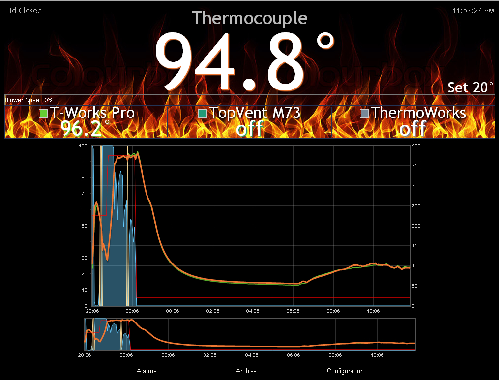
Here is a screen shot of the thermocouple with the external amp and a ThermoWorks Pro thermistor probe from the cool evening last night through the warm day today. They track very close, though the thermocouple has a quicker response so you see it react a bit more to temperature changes caused by sunshine/clouds etc when the fire isn't burning. I still have yet to see the noise indicator pop up even while sending the probes over the very long CAT5 cable, which is of coarse good news, I guess those RC filters are really doing their job!
ExternalAmp.jpg
 
Last edited:
Doing some heavy basting tonight with the ThermoWorks Pro thermistor probe next to the thermocouple, thermocouple amp is outside on the end of a very long CAT5 cable... All of the ups and downs in the temperatures presents a good opportunity to track the response....
TWX.jpg
 
vput09.png


Bryan sent me a 4.2.4 to test with a larger blower(Delta BfB1012HH, 28CFM)

Had some problems with soldering the SMD thermocouple parts, my suggestion to soldering them is to get a liquid rosin flux like MG Chemicals. its very sticky and it acts like a glue, holding the parts where they need to be and helps with soldering. Also, putting a little bit of solder on one of the pads of each component before lining up the part. My 2nd try at the soldering(with the rosin flux) was better, could have been great, if I did not have to remove the first parts.

I do have one problem though, but to me its not an issue. Last night while was testing the thermocouple in boiling and ice water. It was perfect all the way to 211 and when I put the TC in the ice water the temp stopped at 59 degrees and would not go any lower. I removed the TC and soon as it reached 60 again it was fine. So some reason 59 is the minimum with the pit TC. My Food probes did not do this and my Thermoworks probe did fine from 32 to 211
 
I haven't tried anything below room temperature with the thermocouple. I'll give it a try tonight but it should be good down to roughly 5C or 41F before it stops reading lower. If you've still got mV/C not set to 5 then this could be an artifact of that, and I'd say you should investigate that issue first.
 
I haven't tried anything below room temperature with the thermocouple. I'll give it a try tonight but it should be good down to roughly 5C or 41F before it stops reading lower. If you've still got mV/C not set to 5 then this could be an artifact of that, and I'd say you should investigate that issue first.

Hmm, funny you should say that, cause the other night I put the thermocouple into my cocktail and it went down to exactly 41F as I recall, I thought my drink just needed more ice! LOL (HMv4.2.3)
 
It probably varies some part-to-part, but the datasheet says -Vs+0.025V as the minimum which would be 5C. A quick test with some salt ice water and mine does 38F (3.3C) which is roughly 0.017mV. 59F (15C) which is 0.075V is way outside of spec.
 
Today I finally got a chance to dig in and examine the little thermocouple board that came with my HMv4.1 board. Although this was an unsuccessful prototype thermocouple amp, the circuit structure is pretty similar to the working thermocouple amp that is found on the HMv4.2 boards. Their are quite a few component value changes, and two additional resistors added to the HMv4.2 circuit.

I found the easiest way to modify this board to match the new circuit was to first cut the trace between the 1nf cap and the 10K resistor (where the red dotted line is in the picture below). You have to ignore the component values silk screened on the board and install the values I have added in the pic (values from the HMv4.2 circuit) then add the two extra resistors shown. I chose to use through hole resistors because I found that to be easier. I built and tested this circuit tonight and it is working great.

Here is a pic of the HMv4.1 thermocouple amp board with the above modifications detailed:
HMv4.1_to_HMv4.2_ThermocoupleAmp.jpg

Note the black X on Pin4 of the thermocouple amp, that pin is not used so you don't have to worry about soldering it. Also note that Pin2-3 are bridged (and are gnd), and Pin5-6 are bridged as well (this is the output), so you don't have to worry about clean solder between those pairs of legs on the IC

And here is a pic of the actual board all built up:
HMv4.1-2ThermoBoard.jpg


So this board could be modified and used as either an external thermocouple amp, which can run outside the HM which will allow you to send the thermocouple output through the CAT5 cable with the blower and servo, or it can be used to add thermocouple pit probe support to pre v4.2 Heater Meters, or it could be used to add a second thermocouple input to a HMv4.2. I'm really happy how it worked out.....
 
Last edited:
Here is a pic of the HMv4.1 thermocouple amp board with the above modifications detailed:
HMv4.1_to_HMv4.2_ThermocoupleAmp.jpg

Note the black X on Pin4 of the thermocouple amp, that pin is not used so you don't have to worry about soldering it. Also note that Pin2-3 are bridged (and are gnd), and Pin5-6 are bridged as well (this is the output), so you don't have to worry about clean solder between those pairs of legs on the IC
Oh man that's a really awesome diagram there and super-creative to swap the (marked) 1M / 0.01u components like that. The 10k surface mount resistor is 1k in the HeaterMeter v4.2.4, but that value really depends on the what noise you see on the line.

As a caveat to others, the TC- and TC+ should be as close as possible to the thermocouple plug, ideally soldered right to it. The 3.3V/Out/Gnd are the wires that should should be extended if needed.
 
If you are using this as an external TC amp I think the best way to hook up the TC connector would be to lay it right on top of the board and solder the legs right to the two resistors. A touch of hot glue or silicon or some tape or shrink tubing could hold them together. That would make a nice compact unit and having the TC amp and connector bound together like that will keep them the same temp and therefore give you the most accurate temp readings.

That said, I used an inline TC connector with a couple inches of copper (CAT5) wire between the amp and connector and that is working fine for me. Apparently the output of the amp is much more forgiving of the wire type because it seems to work fine over a 50+ foot CAT5 cable when you send the amp output, I don't even get any noise, but if you send the raw thermocouple output down the same cable you would need to set a massive offset to compensate the inaccuracy.

If you are going to put the amp into the HM instead, you could get a panel mount TC connector and make a slot on the HM case to install it, and connect the resistor legs right to the connector if possible (should be doable), the rest of the connections should be fine to run through copper wires to the HM board from my experience.


Back
Top