Heater Meter V4.2.3 build questions


Golly. That's... unexpectedly good performance. How accurate is that temperature?

Well, that's a good question...
I just put another 732 along side this one and it is reading 23.9, and a Thermoworks Pro is reading 31.4... So the two 732's are reading right in line with each other, but I would venture to guess the Thermoworks is giving the more accurate reading, since ice water should settle out at right around freezing.... though the glass is a little heavy on ice.... Still I am extremely impressed by the performance with the previously troublesome Maverick 732 probes....
 
Golly. That's... unexpectedly good performance. How accurate is that temperature?

Yah, and I just took the iced probes outside and plugged them in through the long CAT5 cable and they're all still registering, that's just outstanding!

It is kinda hard to get a good solder connection on those spare rj45 legs to jumper the probe leads to though, if there is any way you could facilitate an easier connection on the next HM board that would be nice....

I also added a Maverick 73 probe to the mix and it reads almost identical to the Thermoworks, so I'm pretty sure that is the more accurate reading....
 
Last edited:
Running the HMv4.2.3 board again tonight and still quite impressed... Since the noise level on the probe lines is reduced so much the HM responds more gently in a more linear manner, rather than jumping around 'cause it thinks the pit temp is jumping around. Here is a graph of three probes over the long CAT5 cable, 1 hour scale zoomed in, this is a live scroll not a refreshed smoothed out view.

HMv4.2.3Probes.jpg


Probe1 is a Maverick 73 and it is clipped together with Probe3 ThermoWorks Pro, they are clipped to the grill grate, I put a few degrees offset between them because the lines were so steady and on top of each other you couldn't see them both! Probe2 is a Maverick 73 stuck in the top vent. I love to see how linearly the blower/servo is ramping up with this build, again, stability, AWESOME!
 
Yes the LCD on that board is 0.025" closer to the front edge of the board. The left screw hole is 0.75" from the left side of the board however the screw hole in the v4.2.4 is the same distance, but the left edge of the board is expanded to left 0.025" so the screw hole moves with it.

I have a mock up of the 4.24 case and by the specs for the display and board, the display in 0.57 mm off center to the right. Obviously this is imperceptible to most people but I just want to make sure that I am correct in my calculation. The only thing I am unsure of is for the 4.23 board, is the LCD position relative to the left edge the same as in the 4.24 board or is it 0.635 mm closer?

EDIT: I meant 0.635 mm
 
Last edited:
Well that's complicated! The LCD is in the same X position in 4.23 vs 4.24, but the left edge of the PCB is moved that 0.025". So technically the LCD is 0.025" more right of the board edge, but relative to the RPi connector (which is my reference point) the LCD X position is the same. I don't think the extra PCB added to the left should affect the X offset of the LCD in the case.
 
I placed a bezel around the LCD. I have 2 options that I am back and forth on. One where the bezel goes to the edge of the display and one where it opens a bit more to see the metal bezel of the LCD itself. I am taking an informal poll. Do you like 1 or 2 better? I am leaning towards 2 because the new boards are a bit wider and I think the wider LCD opening offsets that a little bit.

EDIT: After looking at the pics I think I favor 1

1
14429744884_3c056b8cf0_c.jpg


2
14244277770_f9a4a48ba3_c.jpg
 
Last edited:
I have no opinion other than picture 2 looks neat as the hole for the button is right where the camera would normally be on the phone, which is caught in the reflection.
 
I like option 2, with bezel shown. Although, as with all good things, don't show too much bezel, just enough to make it interesting! Thx, Tom
 
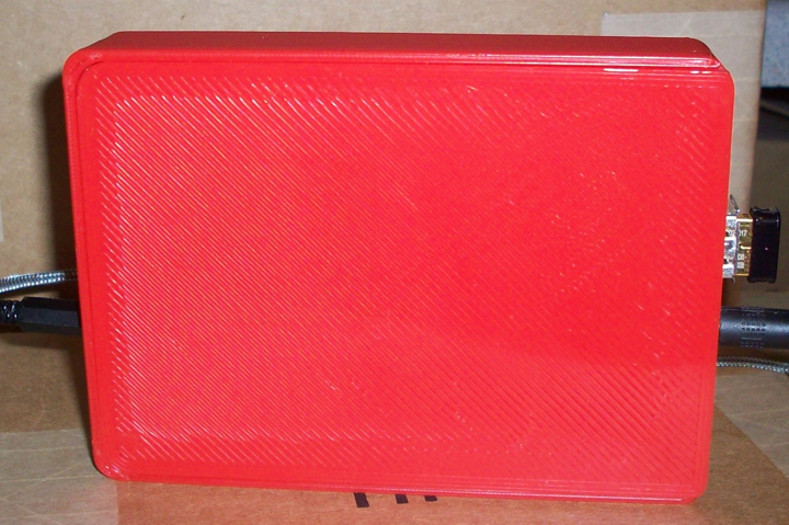
Ever since I built my 3D printer I wanted to take a stab at designing a Heater Meter case, but Tom and Matt make such nice case designs I've just been using theirs. At this point my 3D modeling skills have come along a bit, and since I have here a prototype Heater Meter board I thought this would be a good time to dig in and give it a try. Of coarse I wanted to do something different, so I shot for an ultra small press fit case, this is what I come up with so far....

HMv4.2.3Case.jpg


HMv4.2.3CaseRSide.jpg


HMv4.2.3CaseLSide.jpg


HMv4.2.3CaseBack.jpg


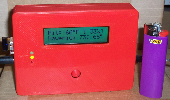
Here's a pic of the unit next to a Bic lighter as a common reference of scale:

HMv4.2.3CaseBic.jpg


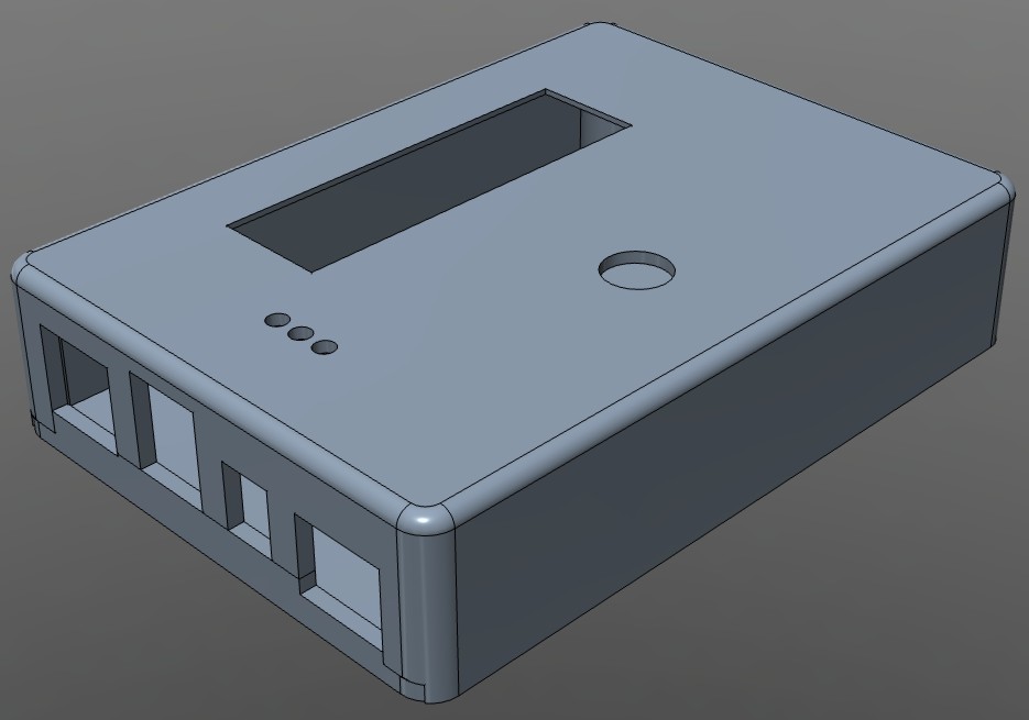
Instead of cutting the case in half I made the case body one big shell, you insert the probe jacks into the holes on the case and then rotate the board set down into the other side of the case. It works out really well on this board set I have here.

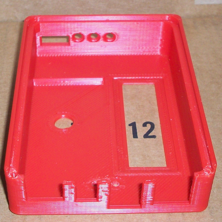
Here is a pic of the empty case:

HMv4.2.3CaseEmpty.jpg


...and a pic of the board set going into the case:

HMv4.2.3CaseBoard.jpg


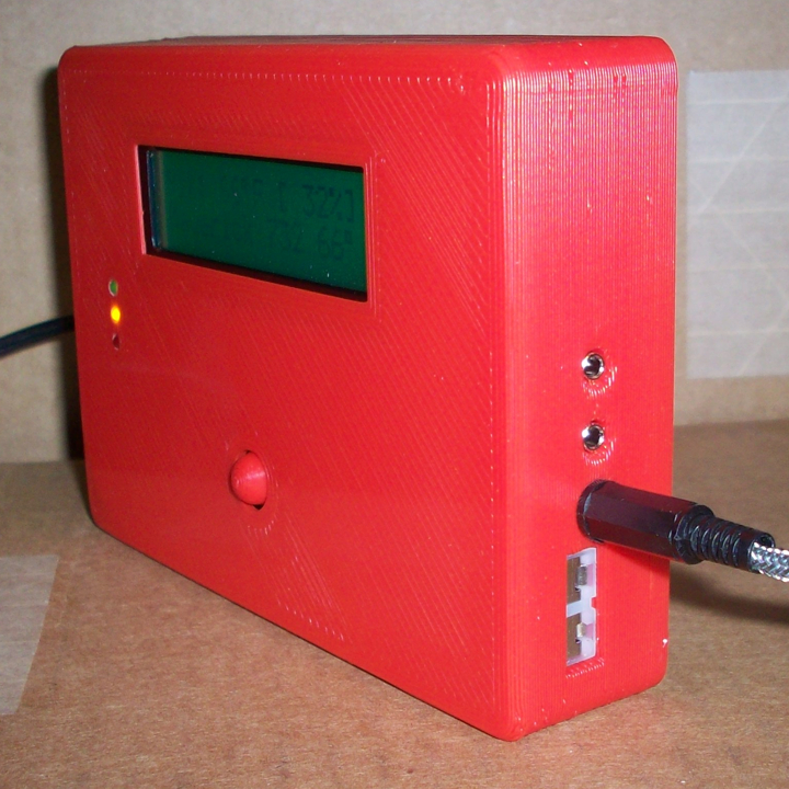
I've had great success withe press-n-fit objects with the roto-damper so I thought I would give that a try. Unfortunately that works much better on round objects than square. The first back I tried was just flat, it did press-fit and hold in place but not to my liking. I've tried a couple other ideas.... this one has pegs in the back that push into the case, though that is a kinda fragile deal so I am shying away from that. What I have here works for me and is pretty solid, I don't worry about it falling apart, but I will brainstorm on it for a while and see if I can come up with a better press-n-fit design before Bryan makes the official release of the HMv4.2.X board. If all brainstorming fails I will put two screws through the back on the side with the rPi I/O where the pegs are now. I'm thinking the mounting screws they supply with the servo would be a nice easy option, since I don't need them with the roto damper, or anything similar. It doesn't need to hold much since the case and back mate nicely and the press-fit already holds things in place.

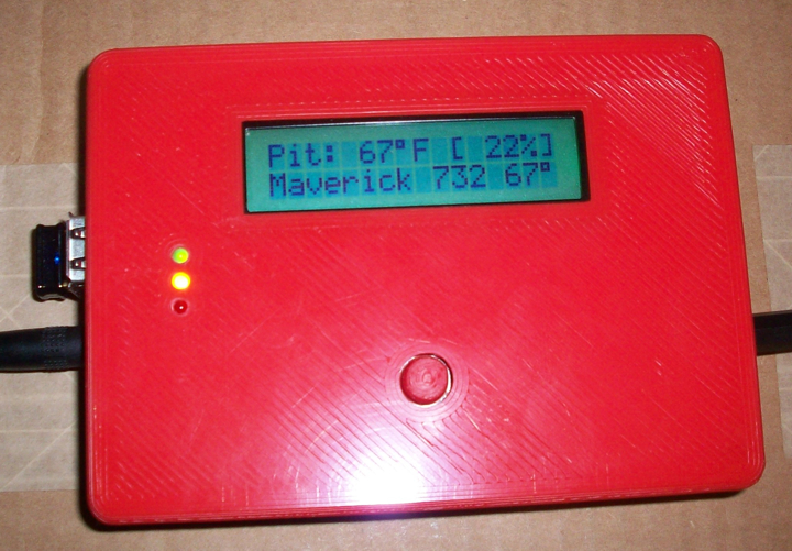
Since the LCD is up there so high on this unit the stock button for the switch stuck up pretty high and looked kinda obtuse, so I designed my own button nub, I'm really happy how that worked out. It sticks out just enough to activate with your finger and I think it looks really good...

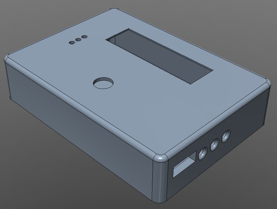
Here are a couple of pics of the object from the 3D modeling app 123Dbeta...

HMv4.2.3123DCaseR.jpg


HMv4.2.3123DCaseL.jpg


All in all I am pretty happy with how it came out, but like roto damper and Heater Meter itself, this is a work in progress and I think it will evolve over time...

Here is a link to the STL's in case anyone wants to check it out, remember, it's a work in progress....
 
Last edited:
Ha, I like your button nub! Lookin' slick too.

Yah, I'm pretty happy with how it worked out, specially the button nub! I just linked the STL's in the original post in case you (or anyone) wants to try out the case or the button nub. I sliced the case really rough at .4mm first layer and .5mm for the rest to get a fast print and it worked out pretty well (as pictured, printed with a .6mm E3D hotend)...but I had to slice the button nub at .2mm to get the top to be round, when the slice is more course the top ends up more pointed than round like the one pictured.


Back
Top