John Bostwick
TVWBB Wizard
Looking forward to this board, already have the parts for it except for the thermo components
The problem is because the new firmware uses a different format for the debug log messages that isn't compatible with the linkmeter version you have. When HeaterMeter sends out a debug message it crashes the linkmeterd which causes you to "lock up" in that no web pages work after that (and won't work on reboot either because it just keeps crashing).
Yeah the linkmeter package from the development machine works ok with avr debug in either old or new format
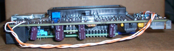
Ralph, can you post a profile pic of the device so that I can see the top of the LCD and button cap in a horizon view.
Actually, now that I look at it I think perhaps the contrast control may be an issue... It's up there pretty close to the face of the LCD, just about 1.5mm from the top of the contrast pot to the surface of the LCD. Maybe we should flip the assembly and put the LCD on top of the HM board instead of underneath? How thick do you go on the face of the HM cases?
Edit: I guess you could just make a shallow spot on the inside face of the case to accommodate the LCD contrast pot, seems easier to me than pulling this LCD off the HM board now that I am contemplating it... LOL If you think this is the way to go and need any dimensions from me just let me know. I think Bryan was trying to slim down the board set as much as possible on this version, if we can keep the LCD on the bottom side of the HM board and make it fit into a case it should work out to be quite slim indeed...
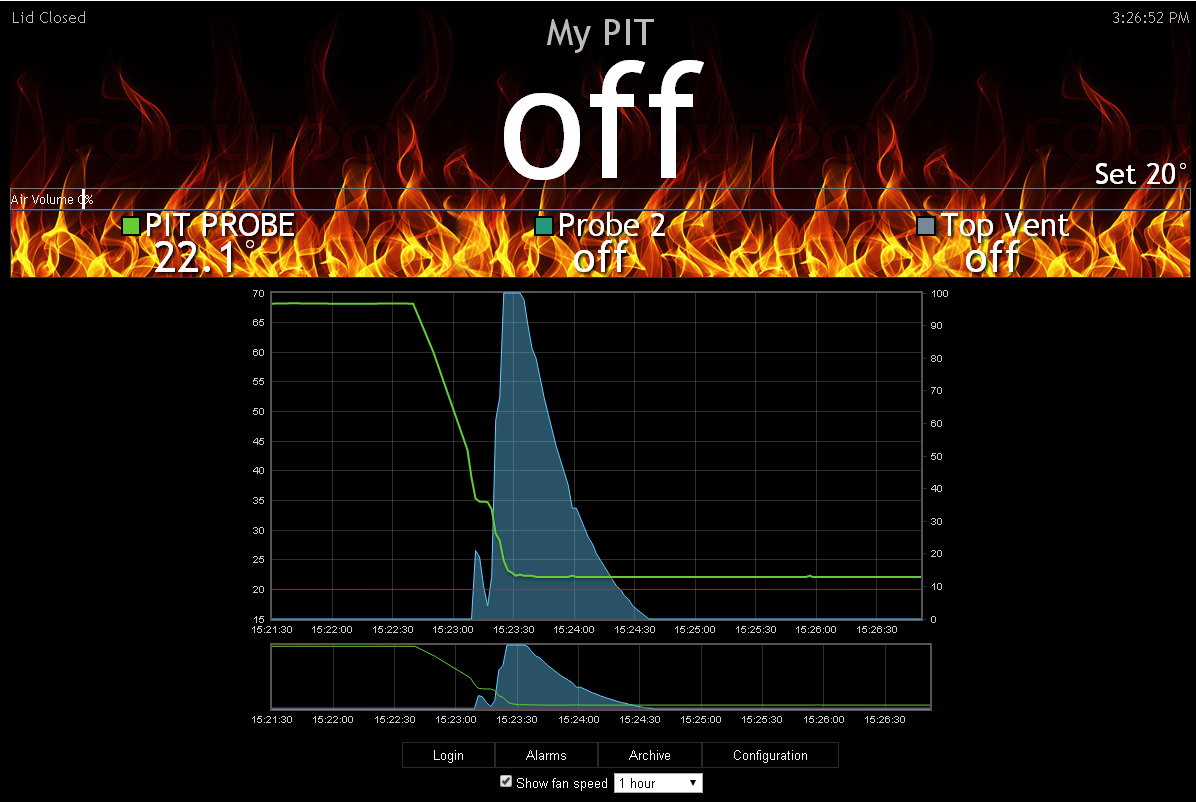
Golly. That's... unexpectedly good performance. How accurate is that temperature?Bryan, I just put a Maverick 732 probe on ice and it went down to 22.1 degrees with rock solid temperature readings.... being the probes that like to drop off at room temperature this is outstanding performance! I'm loving how smooth the graphs are looking on this new board, I'm not looking at the noise monitor on my screen but I can tell from the graphs and lack of drop outs that the probe signals are much cleaner...
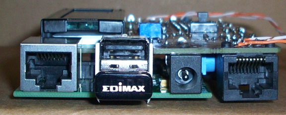
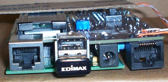
Bryan, Ralph's board has the LCD offset 0.635 mm compared to the semi-final version that I am modelling, correct? If so, Ralph, I will be sending you a custom stl that only fits your board but it will be able to judge the fit of all the other components.
Send it to me too! I have one as well with these dimensions, and if you're going to make a case for it I'll print one and give it away as part of the 4.2 release party.Bryan, Ralph's board has the LCD offset 0.635 mm compared to the semi-final version that I am modelling, correct? If so, Ralph, I will be sending you a custom stl that only fits your board but it will be able to judge the fit of all the other components.