Bryan Mayland
TVWBB Hall of Fame
Oh I guess you don't have to force it, as I just did it and it worked. Just go to System -> Software and paste the URL in the "Download and install package" box.
Yeah isolation means you'll need a transformer, and HeaterMeter itself needs about 25-50mA but it has to power the Pi too which means like an amp on the 5V side. The size of that transformer makes it impractical unless one was going to build the 12V power supply into the HeaterMeter case. You'd need something like this 5V supply except in 12V form. EDIT: 12V form.Well, I was thinking the isolated DC-DC 5V regulator would isolate the electronics from real ground (that you touch with your feet etc), but leave the 3.3V and 5v on the same "lifted" ground, since the 3.3v is regulated from the 5v. I would guess the reason for the larger size of the isolated unit is some sort of transformer, no matter how you slice it a transformer is gonna be a large-ish item compared to most of the parts in the HM....
Just thought I would throw that idea out there after I noticed the DC-DC we are using is non-isolated, which made me realize there must be other versions that are isolated... How much current on the 5v line do we need to run the HM?
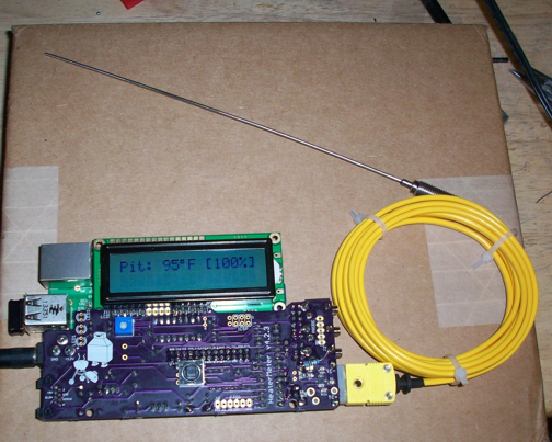
haha oh I forgot to tell you about this. Because the coefficient shares the same "slot" as a steinhart coefficient, that number isn't right at all when you change probe types. The AD8495 is a 5mv/C amplifier so the number should be 5.I assume I need to adjust the mV/C setting for the thermocouple, so I dropped a "0" and went from 10,000 to 1,000, now I am reading about 95 degrees in a 78 degree room.... Any hints on how to get the right setting for the thermocouple would be appreciated....
This is related to any time difference between the HM and your machine, as well as the whims of the browser cache. When the page loads it contains the latest HeaterMeter data along with the timestamp of the data. If there is a difference in time, the code queries for new data and has to wait for it to arrive which is that lag you see. If the browser displays the page from cache, the data will be old as well so it has to query it too. If everything is perfect it looks seamless but if anything goes wrong along the way you get that 1-5 second lag. I think in your case the DNS was preventing the time from syncing so your browser kept refreshing the data.One other thing, when the HM home page loads the Probe Names, temps and setpoints are all blank for a few seconds then they all appear, kinda lagging each time I come in/out of config or load the home page. Not sure what that issue may be?
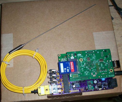
hope to test this baby out soon, but I'm not used to running the HM boards without a case, back to the tupperware for now I guess....
You should have a design to test by the end of the weekend.
I just emailed you a hex file with the FOOD1 probe controlling the PID.

Told ya the LCD would be messed up
I've sent you another try. It's not an easy change to just use a different probe for control apparently.