HeaterMeter v4.0 for RaspberyPi / Standalone


I'm actually not sure how to not get the network configuration to stick. I've got the wired interface the default static 192.168.200.1 (but no cable plugged in), and the wifi set to dhcp. Save and apply and it persists through reboots. The only thing I can think of is that the pi can't write to the SD card? If that was the case I would expect you'd see a lot more issues than just configuration reverts though.

Maybe set the configuration then check /etc/config/network to make sure it has the right information in it before rebooting?
 
I played around with the config a bit more and ended up setting the wired interface to not load at boot. It fired up with my wifi address more than once, so I think I'm good to go there.

I then made an entry in my router to port forward traffic from outside to inside on port 80. Combined with the dyndns account I already had set up, I'm now able to see the unit from anywhere. Wheeeee!

One quick question for you on probe config - the values I'm seeing are sane, so is it safe to assume the default probe coefficients are set for the Maverick probes?

Thanks for all of your work on this!!!
 
Yes the defaults are for the Maverick ET-72 probes. You'd know if you had the wrong coefficients because the values would be seriously out of whack if they displayed at all. Good to hear you got it working!
 
That's pretty neat, where did you get it? I have had an incredibly hard time finding boxes that have nice bezels for the LCD so it doesn't look all ghetto poking through the case. It is really strange that the NewHaven doesn't match the LCD standoff footprint. I have a handful of other 16x2 LCDs and they all have identical hole placement.

The foot print does match if you order part number a9074309 it is for the Compact LCD in the M size Case, Just Place my free sample order.
here are the drawings to match up the size. top version III is compact display. http://www.okw.com/okw-static/drawings-pdf/00001941.pdf. and http://www.mouser.com/ds/2/291/NHD-0216K1Z-NSW-FBW-L-4844.pdf.

Order from the data sheet part numbers http://www.okw.com/okw/pdfs/e/st3720i.pdf
 
Last edited:
The foot print does match if you order part number a9074309 it is for the Compact LCD in the M size Case, Just Place my free sample order.
here are the drawings to match up the size. top version III is compact display. http://www.okw.com/okw-static/drawings-pdf/00001941.pdf. and http://www.mouser.com/ds/2/291/NHD-0216K1Z-NSW-FBW-L-4844.pdf.

Order from the data sheet part numbers http://www.okw.com/okw/pdfs/e/st3720i.pdf

Thanks. I will see if I can exchange the units.
 
Can the switch also be soldered via wires to the board? Or does it have to be soldered directly to the board? My friend is coming over Thursday to help me put this together and I want to make sure I have everything setup and ready to go.
 
The 4-way button? Yeah wires work great. You'll only need 5 wires as there are only 5 connections out of the 6 pins. The top right hole in the PCB (looking from the top with the power connector bottom left) does not need a wire.
 
The 4-way button? Yeah wires work great. You'll only need 5 wires as there are only 5 connections out of the 6 pins. The top right hole in the PCB (looking from the top with the power connector bottom left) does not need a wire.

Great! I bought 22 gauge wire to connect everything. That should be good? Also, I couldnt find 70/30 solder like I was told to get and ended up with 63/37 I believe.
 
Ok, 4.0, here I come, anyone have a single board for sale?

Question about the wireless capabilities as well, is there routing capability like before or just the ability to connect to a single network? Is there client and AP modes before with a DHCP server?
 
Question about the wireless capabilities as well, is there routing capability like before or just the ability to connect to a single network? Is there client and AP modes before with a DHCP server?
I'm not sure about the routing capability if you wanted to use the device like a firewall but it may be possible.

It does have both client and AP mode, but the DHCP server has to be installed manually. Good news though, unlike the WRT54GL, you can install any package from the standard OpenWrt package repository (that's the RC1 but there will be one for final too). That package is dnsmasq.
 
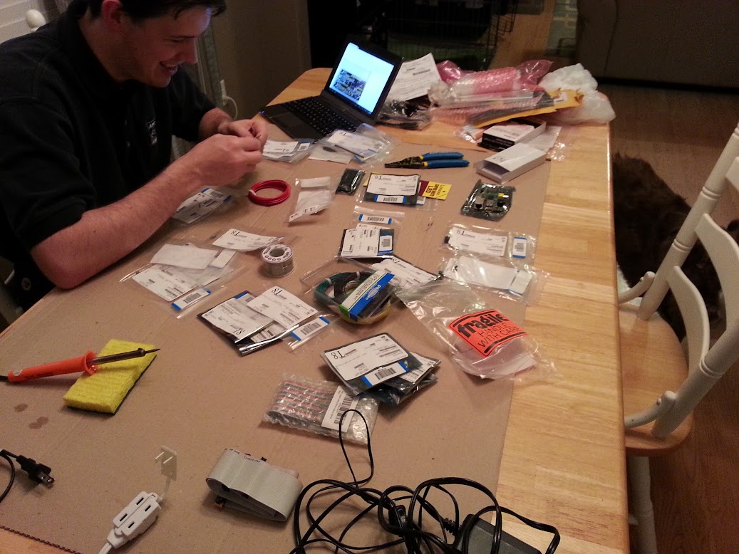
Well we started the build today.


All the parts and my buddy the engineer who did a fine job soldering with my $5 iron from harbor freight.

20130124_194142.jpg


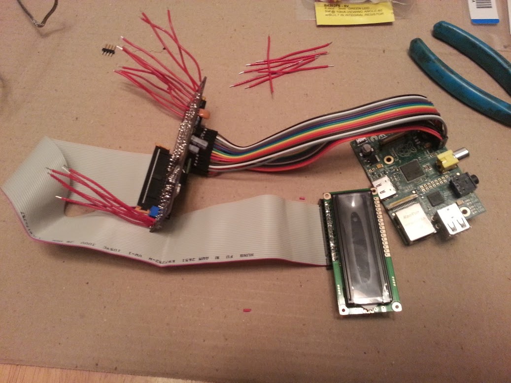
We got everything but the case mount stuff done tonight. So that means the leds, 4 probe sockets, rca jack, dc jack, and...I think that is all. I have a floppy cable connecting the lcd and bread board cables connecting the Rpi to the HeaterMeter board

20130124_222130.jpg


Here are two closer shots of the board:

20130124_222159.jpg


20130124_222209.jpg


After seeing how much cabling and wires there are, I am starting to get overwhelmed about mounting in the case I bought. I think I am going to break down and 3D print the case and put it together the normal way. Thankfully I bought all the standard jacks along with the panel mount just in case this happened.
 
I'm not sure about the routing capability if you wanted to use the device like a firewall but it may be possible.

It does have both client and AP mode, but the DHCP server has to be installed manually. Good news though, unlike the WRT54GL, you can install any package from the standard OpenWrt package repository (that's the RC1 but there will be one for final too). That package is dnsmasq.

Thanks Bryan, I don't really need routing per se but here's my issue: When I use it at home, I want it to be a client to my home network but when I use it at a cook-off I want it to act as an ap with dhcp so I can connect my phone or tablet. Any thoughts on easily switching? 2 SD cards maybe with different configs or 2 wireless adapters????? Also, should I pay the extra for the 2.0 board with more memory?
 
Last edited:
Oh snape! Here's a tip, you can remote all those wires on the probe side, and use the 5 pin header that's there for this purpose. The ground wire you wire to one jack then dasiy chain it to each of the other jacks, then you run one of the wires to each probe, sort of like this (except I haven't run the black wire, ground, back to the header yet, and there's only 3 probes here):
linkmeter-2011050704.JPG


And mounted to the panel. The ground wire can be seen here leaving off to the left:
linkmeter-2011050705.JPG


It would really cut down on the clutter because you'll only have 5 wires instead of 12.
 
When I use it at home, I want it to be a client to my home network but when I use it at a cook-off I want it to act as an ap with dhcp so I can connect my phone or tablet. Any thoughts on easily switching? 2 SD cards maybe with different configs or 2 wireless adapters?????
2 SD cards would be a super easy way to maintain separate configurations, one with AP mode and one with client mode. I think you could actually do the two wifi adapters as well, although I've never tried it.

The other option would be to put a script into the System -> Startup -> Local Startup that swaps the configuration each time you reboot or something.

Good info Bryan, thanks!

looking for a RasPi now............
 
Last edited:
Bryan,

Greetings! I'm really interested in building a heatermeter 4.0. I haven't gotten my smoker completely together yet - maybe this Spring when the weather gets warmer. But I'm pretty handy with a soldering iron, so your end of the project will be my natural entrance to the smoker/BBQ world.

I've played around with Arduino Unos before for some embedded projects. I was looking over your schematics and noticed you're driving the 328P-PU @ 3.3V. I've always used 5V for them. Just out of curiosity, is there a reason you've chosen 3.3V? My first guess would be to cut down on power consumption. Or does it have something to do with the raspberry pi interface? Not really sure as I've never fooled around with a rasp pi.

Sorry if these questions have already been answered, but the search function wasn't giving me any useful results. :(

Overall I'm really impressed with the efficient layout and functionality of the PCB - I can tell you've put a lot of time into this project.

Sending the files over to OSH Park tomorrow, hopefully I'll get the PCB's back mid Feb.

Thanks for putting this project online!

Matt


Back
Top