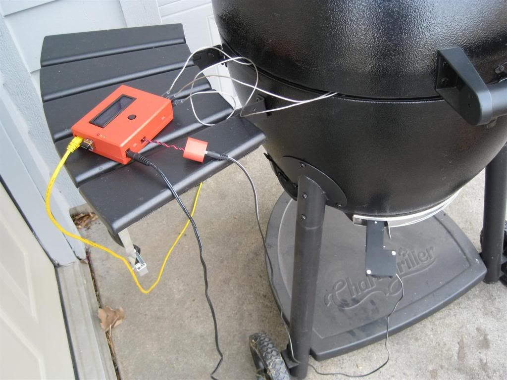
HeaterMeter v3 used all panel mount jacks and these are the jacks recommended then:
Mono 2.5mm jack
RCA female jack
both from Mouser
The DC power jack can be panel mount too, but there's no pinheader for it so you'll have to solder directly to the footprint (which is pretty huge so it shouldn't be a problem). For posterity I'd say you can actually just wire it to the probe ground connection and 12V fan connection, but it is easier to say it should go to the existing footprint.
You can power the HeaterMeter board from the 5V microusb jack on the Pi, but that only gets you 5V so the fan won't operate at that voltage. An easy way to test the board without powering it from 12V though.
Yes you can use those wires to connect the pi/heatermeter. The schematic lists the only wires that need to be connected, but connecting them all doesn't hurt.
Here's the LCD connector. You can't mess it up really, just connect the red stripe to pin 1 on both and figure out which side of the plug you're using. If you've got the right set, the LCD will light up (once HeaterMeter is running on the AVR), if not, then it will stay dark. If you've got it the wrong way, nothing can go wrong so don't worry about messing up.

EDIT:
NOTE! this LCD in the photo has the pinheader soldered to the top half, but the recommended LCD has contacts on the top and the bottom so it is your choice depending on the final layout you want.


