Bryan Mayland
TVWBB Hall of Fame
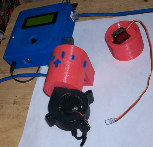
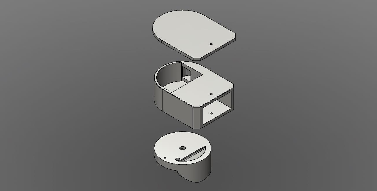
I got at least to the usable state with my design. Goals were to hopefully allow more airflow when the blower is off and the damper is open. To that end I've made a large exit area to reduce restriction. Another goal is to be 60mm tall (blower height) and under 2" wide (to make it easier to slide onto the BGE). The blower is also designed to be removable.
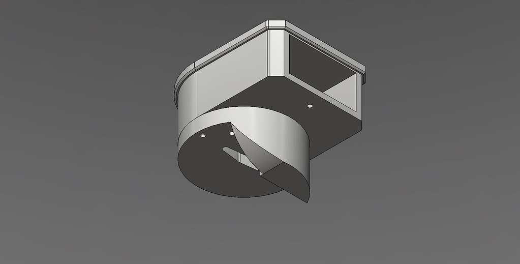
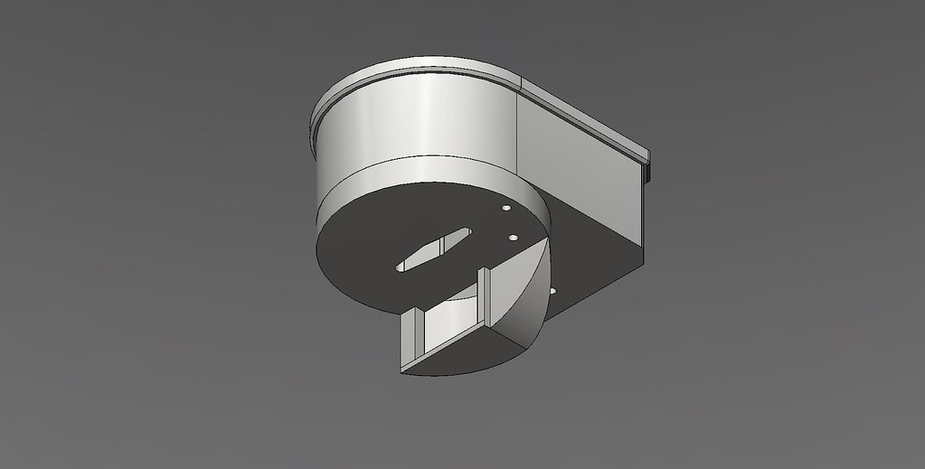
Profile

Closed

Open

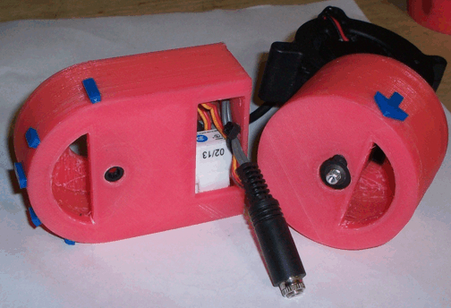
Fan removed

I'd like to integrate the RJ11 jack, but I'm not sure I like this shape. I might change it to have the servo on the side, make the exhaust taller but thinner.
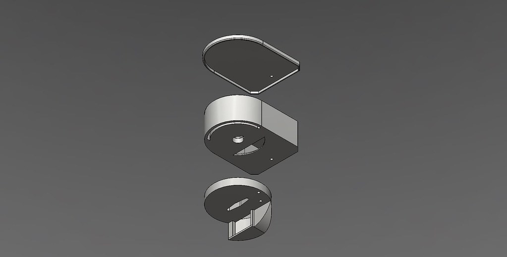
Profile
Closed
Open
Fan removed
I'd like to integrate the RJ11 jack, but I'm not sure I like this shape. I might change it to have the servo on the side, make the exhaust taller but thinner.