LinkMeter v2 Homebrew BBQ Controller - Part 2


Its hard to tell from your picture, but you may be missing a couple of jumpers. I think its 1-5 and 15-2, but check out the schematic and you can see them on my picture: http://tiny.cc/bnqrfw

Neil

Originally posted by Kyle Stierwalt:
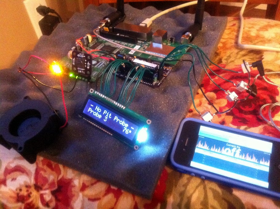
Thanks, Neil, appreciate the help...when I adjust this to the point where "character boxes" show it basically just fills each box with pixels, so I guess I should say each box is black, not blank.

I'll take a picture tonight when I get home after work.

<BLOCKQUOTE class="ip-ubbcode-quote"><div class="ip-ubbcode-quote-title">quote:</div><div class="ip-ubbcode-quote-content">Originally posted by Neil Mager:
Adjust R6, its the contrast for the lcd display.
Same issue alot of us ran into!

<BLOCKQUOTE class="ip-ubbcode-quote"><div class="ip-ubbcode-quote-title">quote:</div><div class="ip-ubbcode-quote-content">Originally posted by Kyle Stierwalt:
Have everything done on the PCB and flashed the AVR; the router is up and running with LinkMeter code. Plugged in probes and they are working/registering. Everything works except the LCD, getting power as the back-light is on, but just a blank screen. I've dug around on the forum a bit but wondering if anyone else has seen this and knows a fix. Here's a pic.

Thanks.
</div></BLOCKQUOTE> </div></BLOCKQUOTE>
 
Originally posted by Neil Mager:
Its hard to tell from your picture, but you may be missing a couple of jumpers. I think its 1-5 and 15-2, but check out the schematic and you can see them on my picture: http://tiny.cc/bnqrfw

Neil
Are you talking about that jumper you have on the top of your LCD? I have no jumpers on my LCD and it works fine.
 
Are you talking about that jumper you have on the top of your LCD? I have no jumpers on my LCD and it works fine.

The jumpers are optional and throw back to previous builds. You can either wire up all the connectors 1-6 & 11-16, or you can leave out 15 & 5 and jumper them directly on the LCD.
 
Originally posted by J. Winn:
Bro tip: Solder your resistors to the bottom of the button board. Otherwise you won't be able to get it to mount flush enough to have the button protrude through the router casing. Unrelated but when I saw your picture it reminded me because I just did my button board last night.
The resistors are smaller than the height of the button base, so the base hits before the resistors do. How does putting them on the back help? Also, did you include the button cap in your installation? It adds quite a bit of height to the point my button board is actually mounted on some standoffs.
 
Originally posted by N Waring:
The jumpers are optional and throw back to previous builds. You can either wire up all the connectors 1-6 & 11-16, or you can leave out 15 & 5 and jumper them directly on the LCD.
This is exactly true. The old connector only ran the minimal amount of wires to the LCD and relied on you doing some wiring at the LCD, but the v3.1+ boards have all the wires connected just from the HeaterMeter board.

If you've flashed the wrong HeaterMeter firmware version the LCD won't show anything. Assuming you have a v3.2 board the version number on the configuration page should end with a B. You can also try flashing from the "online repository" option of the "AVR Firmware" tab of the website.
 
Originally posted by Bryan Mayland:
<BLOCKQUOTE class="ip-ubbcode-quote"><div class="ip-ubbcode-quote-title">quote:</div><div class="ip-ubbcode-quote-content">Originally posted by J. Winn:
Bro tip: Solder your resistors to the bottom of the button board. Otherwise you won't be able to get it to mount flush enough to have the button protrude through the router casing. Unrelated but when I saw your picture it reminded me because I just did my button board last night.
The resistors are smaller than the height of the button base, so the base hits before the resistors do. How does putting them on the back help? Also, did you include the button cap in your installation? It adds quite a bit of height to the point my button board is actually mounted on some standoffs. </div></BLOCKQUOTE>

It sounds like I may have mounted mine differently. I will take some pictures when I get home. Yes I used the cap. Do you have pictures of how your button is mounted with and without the cap?
 
Originally posted by John Bostwick:
<BLOCKQUOTE class="ip-ubbcode-quote"><div class="ip-ubbcode-quote-title">quote:</div><div class="ip-ubbcode-quote-content">Originally posted by Shane Woessner:
This is probably 6th time using the linkmeter. Only thing I can come up with is that I was trying to run my smoker at 325° where I usually run it at 225°. The linkmeter might not be suitable for this size cooker
icon_confused.gif

What kind of smoker and size of blower?

I use a 28cfm(BFB1012HH)on my UDS and it has no problem getting to 300+ </div></BLOCKQUOTE>

Reverse flow offset with a 3'x5' cook chamber and 2' cube firebox using this blower
 
Originally posted by J. Winn:
It sounds like I may have mounted mine differently. I will take some pictures when I get home. Yes I used the cap. Do you have pictures of how your button is mounted with and without the cap?
I don't have this one inside a LinkMeter but 8mm standoffs seem to put it at just the right height. If I were going to mount this, I'd rough up the plastic a little with sandpaper, put epoxy on the ends of the standoffs, and set it in place until it dried.

I should also say that mounting the resistors on the back is fine too, it would work either way in my setup.

EDIT Haha I just realized I forgot to post the photo:
 
Originally posted by Tom Kole:
<BLOCKQUOTE class="ip-ubbcode-quote"><div class="ip-ubbcode-quote-title">quote:</div><div class="ip-ubbcode-quote-content">Originally posted by Shane Woessner:
Reverse flow offset with a 3'x5' cook chamber and 2' cube firebox using this blower

What adjustments to the board did you have to make to use that blower? </div></BLOCKQUOTE>

Not sure what Shane used, but I am using a 28cfm fan and I had to change the IRL510 to NTE2987. Before I made the change the blower would lock up the heatermeter.

The 2987 can handle 20A and the 510 can only handle 5.6A
 
Originally posted by John Bostwick:
Not sure what Shane used, but I am using a 28cfm fan and I had to change the IRL510 to NTE2987. Before I made the change the blower would lock up the heatermeter.

The 2987 can handle 20A and the 510 can only handle 5.6A

Any downside to using the NTE2987 with the suggested blower? I'm just wondering if I could make the system more versatile by being able to switch between use on my bge and larger smoker. Otherwise I'll build another.
 
Originally posted by Tom Kole:
Any downside to using the NTE2987 with the suggested blower? I'm just wondering if I could make the system more versatile by being able to switch between use on my bge and larger smoker. Otherwise I'll build another.
The IRL510 is still the name of the part in the schematic, but the Bill of Materials uses an even better MOSFET with 1/10th the Rds(on) of the NTE2987 and is good up to 60A/60W. I use it with the default blower.
 
I use a 25cfm fan with my board. Initially I had issues where it would freeze the LM, it didn't lock it up completely, just hung the serial driver. I could restart the serial driver and it would resume. I traced this to a couple of issues.

<UL TYPE=SQUARE> <LI>The output driver circuit isn't quite right.
<LI>Ground for the output driver is shared with ground for the serial connection, making it more susceptible to noise injection and corruption. This corruption is what causes the serial driver to hang.
<LI>Poor quality power
[/list]

My HM and LM are connected via a 3 ft cat5 patch cable. I was powering the HM from the LM through the cable. By changing this and providing the power directly to the HM, then back feeding to the LM, I no longer have any issues.

Providing the power directly to the HM, ensures the HM has cleaner power so the ground signal is more immune to noise. If your HM and LM are in the LM case, you could use bigger wires for power/ground and get the same effect. Basically you want a low resistance/inductance connection to help clean up the HM power.

I'm surprised that any of these fans would require a different driver. I know that John had lots of issues and finally found something that worked for him. They are all < 1A fans and the IRL510 is good to 5A.

Here is a link to my fan. It uses about 50% of the power your fan is spec'd at. This helps as well.

http://www.amazon.com/Nidec-Ga...12B6S3/dp/B0025VJEL8

One last thing. I used 24Ga speaker hook my fan to the HM.

dave
 
Originally posted by Bryan Mayland:
<BLOCKQUOTE class="ip-ubbcode-quote"><div class="ip-ubbcode-quote-title">quote:</div><div class="ip-ubbcode-quote-content">Originally posted by Tom Kole:
Any downside to using the NTE2987 with the suggested blower? I'm just wondering if I could make the system more versatile by being able to switch between use on my bge and larger smoker. Otherwise I'll build another.
The IRL510 is still the name of the part in the schematic, but the Bill of Materials uses an even better MOSFET with 1/10th the Rds(on) of the NTE2987 and is good up to 60A/60W. I use it with the default blower. </div></BLOCKQUOTE>

If I had known about that one I would have used it instead of the 2987. alot cheaper. The only reason I use NTE is that it can be bought locally and most stores around the states carry NTE line of parts.
 
@Dave

Actually my fan is 1.10 Amps


Delta BFB1012HH DC12V 1.65A 97x94x33mm Brushless Fan
Rated Voltage: 12VDC. Operating Voltage Range: 4.0 to 13.2 VDC.
Rated Current: 1.10 Amp. Rated Input Power: 13.20 Watt. Speed: 4000 RPM.
Max Air Flow: 28.25 CFM. Max Air Pressure: 1.299 H2O.


if I read that correctly
 
Yeah I saw that. Seems odd that a 28cfm fan is 1.1A, while a 25cfm one is only .3A. That is one reason I bought the one I did.

However, I've found that 25cfm is about 3x what I need for my UDS. I have to limit max speed to 50%, then use my ball valve to really restrict the air flow. But it works great and if I ever need more air flow for hotter temps, I have it available
icon_smile.gif


I should do a test run at 600F to see if I could back pizza.

dave

Originally posted by John Bostwick:
@Dave

Actually my fan is 1.10 Amps


Delta BFB1012HH DC12V 1.65A 97x94x33mm Brushless Fan
Rated Voltage: 12VDC. Operating Voltage Range: 4.0 to 13.2 VDC.
Rated Current: 1.10 Amp. Rated Input Power: 13.20 Watt. Speed: 4000 RPM.
Max Air Flow: 28.25 CFM. Max Air Pressure: 1.299 H2O.


if I read that correctly
 
Hi All,

I thought it about time that I posted a few pictures of my completed linkmeter and fan assembly... https://plus.google.com/photos.../5766182367025051713

The photos are shown from a test run and therefore no food probe is attached.

You'll notice that I've added an barrel jack connector to my fan assembly to aloow me to run it as a blower to speed up high temperature start-ups.

Nick
 
icon_smile.gif
icon_cool.gif

Got a new router today and at first had some issues of flashing the linkmeter to the router. The flash went through but non of the heatermeter stuff was there after fooling around with it I was finally able to get everything working.

And after hooking everything up I have a working Heatermeter, that actually works without having to hit it everytime the LCD screen starts going crazy with gibberish.

Again Thanks Brian for all the hard work you and the others that have made this a fun project and a great BQ controller.
icon_cool.gif
 
Thanks, reflashing did fix my LCD issue. Everything is working except I've just encountered a strange behavior and it's a show stopper. When I plug my pit probe in the LCD goes blank and all the lights on the router come on requiring me to remove the pit proble and power on/off. I disconnected the PCB from the router and powered it by the 12v barrel jack and when I plug the pit probe in under this setup the LED will blink and the LCD will flash quickly and then this repeats over and over. Short somewhere?

Thinking I will solder up a new probe "string" and see if that fixes the issue. Anyway, if anyone else has run into this please let me know, or if you have suggestions on troubleshooting I'd greatly appreciate it.

Thanks, almost to the homemade stoker promise-land.
icon_smile.gif


photo2.JPG
Originally posted by Bryan Mayland:
<BLOCKQUOTE class="ip-ubbcode-quote"><div class="ip-ubbcode-quote-title">quote:</div><div class="ip-ubbcode-quote-content">Originally posted by N Waring:
The jumpers are optional and throw back to previous builds. You can either wire up all the connectors 1-6 & 11-16, or you can leave out 15 & 5 and jumper them directly on the LCD.
This is exactly true. The old connector only ran the minimal amount of wires to the LCD and relied on you doing some wiring at the LCD, but the v3.1+ boards have all the wires connected just from the HeaterMeter board.

If you've flashed the wrong HeaterMeter firmware version the LCD won't show anything. Assuming you have a v3.2 board the version number on the configuration page should end with a B. You can also try flashing from the "online repository" option of the "AVR Firmware" tab of the website. </div></BLOCKQUOTE>


Back
Top