You are using an out of date browser. It may not display this or other websites correctly.
You should upgrade or use an alternative browser.
You should upgrade or use an alternative browser.
INTRODUCING: the "Roto Damper"
- Thread starter RalphTrimble
- Start date

Your graph looks awesome! Seems to be holding steady on your setpoint pretty good... Looks like you were able to drop about 20 degrees from 300 in 10-15 minutes, that's not too bad with a hot ceramic grill. You can use the "choke and burp" method to drop the pit temp about as rapidly as it can go by having the roto damper closed and setting the top vent barely open (or completely closed if your grill leaks a bit), then after a few minutes open the lid to let out the heat and resume normal operation at the lower setpoint. It works for me, but you gotta get to know your grill and how it responds and work from there... but you gotta be careful not to completely choke out the fire..... At any rate, happy smoking!
Or maybe the next great kamado grill add on to rig up to the HM... a blower into a heat exchanger (like a coil of copper pipe) at the very top of the grill or maybe along the inside walls below the grates. You just trickle in the air at the bottom to keep the fire going, but then open another damper and blow full force through the sealed heat exchanger. Even if ambient air temp is 70, that should cool down 250 or 300 degree air pretty quickly. Roto-cooler haha.
RalphTrimble
TVWBB Diamond Member
Or maybe the next great kamado grill add on to rig up to the HM... a blower into a heat exchanger (like a coil of copper pipe) at the very top of the grill or maybe along the inside walls below the grates. You just trickle in the air at the bottom to keep the fire going, but then open another damper and blow full force through the sealed heat exchanger. Even if ambient air temp is 70, that should cool down 250 or 300 degree air pretty quickly. Roto-cooler haha.
I think that is a solution for a non-problem, 'cause the above situation was just a test run of the roto damper to see how it performs. In reality it would be an odd circumstance to have the pit temp set high and then set low, if anything I generally start the pit low and slow and then go higher for saucing, browning etc. Occasionally you might end up with some overshoot, but the best way to control overshoot is to tamp down the fire a bit by whatever method....
Yeah, you don't really put your smoker through that kind of action except during a test of your damper. Besides, people love kamados because of their energy efficiency. It's sort of counter productive to burn fuel wastefully as you remove heat from the system. It's best to just burn what you need.
RalphTrimble
TVWBB Diamond Member
Yah, with a Heater Meter running a damper on a sealed Kamado overshoot should't really be an issue. If you look at the graph above there was basically zero overshoot on any of the four setpoints while raising the temp, and the damper was able to choke the fire down and bring the pit back to 225 from 350 in the end...
I am quite pleased with the results. This was using the default PID, blower, and servo settings (with the exception of the pulse width). I can't imagine needing any other gadgetry. Now, to get a piece of meat in there for some real world testing. The smoke that came out of the top was thin, blue, and wispy. Quite different when you can really open the daisy wheel up.
Bryan Mayland
TVWBB Hall of Fame
Just because the rotodamper design is so dang awesome, I thought I'd see how well a 80mm computer fan worked instead of the blower. The one I picked is quite possibly the worst 80mm fan I've seen in years, because it only turns on reliably at about 8.5V and only pulls 65mA at 12V so you know it doesn't move a lot of air. Still, all I had to do was make a new blower endcap and swapped it out right while HeaterMeter was running. Blue tape to hold it on because I printed the cap the wrong size, waiting on another print right now.


It does an acceptable job, keeping 225F within +/-5F. Probably could be even better with some tuning. I'm going to test the step response once the right-sized version is done printing.
EDIT: Wow this fan is not that great. Running at 100% power all I can get up to is about 250F. It sort of works though, and maybe with a better reducer or a 92mm/120mm fan it could work for a larger temperature range.
Last edited:
RalphTrimble
TVWBB Diamond Member
Yeah, axial fans aren't the greatest at pushing air against any sort of resistance. The best you can do is try to create a vaneaxial fan.
Yah, I find the same thing with axial fans, they don't work well against any resistance or through funneling etc... I haven't tried one on a roto damper, but I made a funnel to focus a small axial fan on my 3D printer head output to improve bridging and I was really surprised how little air moved through it. Even so, the small amount of air movement did improve bridging, but I am going to move over to a blower style fan for that job too so I can move a little more air....
Bryan Mayland
TVWBB Hall of Fame
That's the reason the project uses a blower instead of the more commonly available computer fan. I thought that maybe because with rotodamper I could open vent the top more, and there would be less natural draft restriction through the fan itself, it would be a viable option. You're right though, I think the adequate performance I was seeing was more a function of just the rotodamper itself working than the fan actually doing anything. If it were to work, there would have to be a lot less restriction on the airflow than trying to squeeze 6400mm^2 of fan into 500mm^2 of hole.
The cool part was that to try it I just had to print a different cap for the rotodamper, which is a pretty brilliant design.
The cool part was that to try it I just had to print a different cap for the rotodamper, which is a pretty brilliant design.
RalphTrimble
TVWBB Diamond Member
Thanks for the compliments Bryan, it was an evolution driven by desire to experiment with my 3D printer and learn the 3D modeling programs. The end result was a very effective and versatile design. I have designed at least a half dozen different dampers, the roto damper is the hands down winner, nothing else has even come close...
RalphTrimble
TVWBB Diamond Member
I recently helped someone get a roto damper going and thought it would be a good idea to post the info here in the roto damper thread as well....
In the Heater Meter Config, for Servo Pulse Duration settings.... If you set the low number too low, or the high number too high, it will try to make the servo go beyond it's operational range and it can do all kinds of crazy things like, jam, vibrate, even melt! I don't know what the exact limits are on the servo off hand, but somewhere in the middle of the range is the best way to go.
So take my advice if you want this to go easy...
Separate the body of the roto damper from the barrel
Set the Servo Pulse Duration on your Heater Meter Config page to 800 - 2400 with Inverted Output
Make your Heater Meter go to 100% blower/servo output
NOW mate the body and barrel so the moon shaped openings sit directly on top of each other.
Then make the HM go to 0%, it should close completely. Then make the HM go back to 100%, it should open completely. If you are not getting complete open/close tweak your Servo Pulse Duration numbers SLIGHTLY until you do. The easiest way to tweak the settings is put your HM into the position that is not proper, then alter the number in the Config little by little until it is proper. When you save the config you should see the servo move just a little, if it doesn't move then you probably altered the wrong number....
As for the CAT5 jack wiring....
The HMv4.1.X has the rj45 on board, so the standard HM RJ45 wiring has been defined since then. It is shown on the v4.1 schematic.
Here is a pic of that part of the schematic:
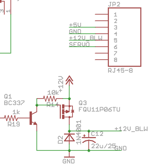
Included in this pic is also the blower driver section, which I posted in the thread about how I converted my HMv4.0 blower driver circuit over to the blower driver used on the HMv4.1 and later. Reason being, V4.0 driver pulsed the ground rather than the positive lead on the blower, so the servo and blower can not share the same ground with that blower driver circuit, so the RJ45 on a HMv4.0 cannot be wired exactly like the above standard. The HMv4.1X driver pulses the positive leg of the blower and uses a regular ground and so the blower can share a ground with the servo as shown above.
If you run a HMv4.0 or older you must dedicate an extra wire for the +12v for the blower. I edited the above image to include an example of what you might use for the HMv4.0 and older and probes:
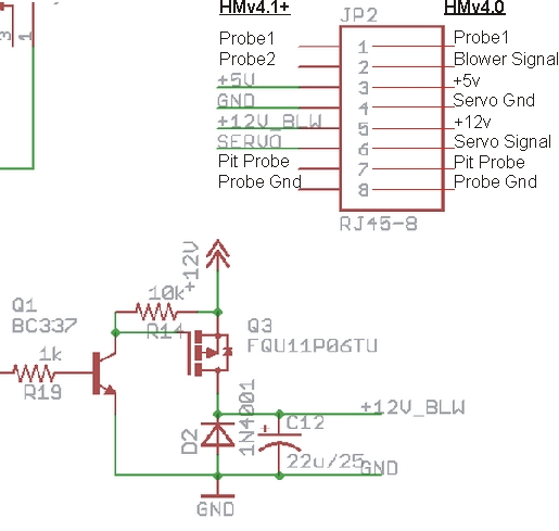
Everything that is not on the end of a green lead in the diagram is somewhat subjective, but it's a good idea to run the pit probe on the same twisted pair as the probe ground rather in the same twisted pair as the power leads or something that is pulsed like the blower or servo signal leads to prevent instability in the pit probe.
If you want to make your HMv4.0 or older run the standard HM RJ45 wiring (so you can use your damper devices on both HMv4.0 and 4.1 units) you would have to convert your HMv4.0 blower driver circuit over to the new HM4.1 style like I detailed in this thread. It was cheap and easy for me to do and has been working great for me. This was important to me cause I work with all kinds of dampers and wanted them to all to run the standard HM RJ45 wiring. If you have a one-off HMv4.0 and a single damper, and are happy with having just the pit probe and one food probe in the CAT5 cable then you could just run the HMv4.0 wiring shown above or something similar....
In the Heater Meter Config, for Servo Pulse Duration settings.... If you set the low number too low, or the high number too high, it will try to make the servo go beyond it's operational range and it can do all kinds of crazy things like, jam, vibrate, even melt! I don't know what the exact limits are on the servo off hand, but somewhere in the middle of the range is the best way to go.
So take my advice if you want this to go easy...
Separate the body of the roto damper from the barrel
Set the Servo Pulse Duration on your Heater Meter Config page to 800 - 2400 with Inverted Output
Make your Heater Meter go to 100% blower/servo output
NOW mate the body and barrel so the moon shaped openings sit directly on top of each other.
Then make the HM go to 0%, it should close completely. Then make the HM go back to 100%, it should open completely. If you are not getting complete open/close tweak your Servo Pulse Duration numbers SLIGHTLY until you do. The easiest way to tweak the settings is put your HM into the position that is not proper, then alter the number in the Config little by little until it is proper. When you save the config you should see the servo move just a little, if it doesn't move then you probably altered the wrong number....
As for the CAT5 jack wiring....
The HMv4.1.X has the rj45 on board, so the standard HM RJ45 wiring has been defined since then. It is shown on the v4.1 schematic.
Here is a pic of that part of the schematic:
Included in this pic is also the blower driver section, which I posted in the thread about how I converted my HMv4.0 blower driver circuit over to the blower driver used on the HMv4.1 and later. Reason being, V4.0 driver pulsed the ground rather than the positive lead on the blower, so the servo and blower can not share the same ground with that blower driver circuit, so the RJ45 on a HMv4.0 cannot be wired exactly like the above standard. The HMv4.1X driver pulses the positive leg of the blower and uses a regular ground and so the blower can share a ground with the servo as shown above.
If you run a HMv4.0 or older you must dedicate an extra wire for the +12v for the blower. I edited the above image to include an example of what you might use for the HMv4.0 and older and probes:
Everything that is not on the end of a green lead in the diagram is somewhat subjective, but it's a good idea to run the pit probe on the same twisted pair as the probe ground rather in the same twisted pair as the power leads or something that is pulsed like the blower or servo signal leads to prevent instability in the pit probe.
If you want to make your HMv4.0 or older run the standard HM RJ45 wiring (so you can use your damper devices on both HMv4.0 and 4.1 units) you would have to convert your HMv4.0 blower driver circuit over to the new HM4.1 style like I detailed in this thread. It was cheap and easy for me to do and has been working great for me. This was important to me cause I work with all kinds of dampers and wanted them to all to run the standard HM RJ45 wiring. If you have a one-off HMv4.0 and a single damper, and are happy with having just the pit probe and one food probe in the CAT5 cable then you could just run the HMv4.0 wiring shown above or something similar....
Last edited:
Dave S (GeoDave)
TVWBB Fan
The roto-damper is just stupid stupid awesome! I wish I could afford a 3-D printer. Another baby or printer...another baby or printer...hmmmmmm
")
RalphTrimble
TVWBB Diamond Member
If you're running a roto damper, or any kind of servo driven damper for that matter, you should check out the latest Linkmeterv10 image release... Among other changes, the servo motion is changed to a much more gentle stepped motion I feel is a huge improvement over the servo motion on the previous release.
Quoted from Bryan's Development log thread on 06-11-2014...
"The latest image release is linkmeter v10 with the associated AVR firmware HeaterMeter 20140320B (accessible from firmware 'online repository/release/10').
The latest avr firmware development snapshot is 20140609B, and the linkmeter package is in the capnbry home builds repository. The release firmware is recommended unless you are looking for good times."
EDIT:
To load the above package, click Configuration, then log in, click AVR Firmware, click Online Repository, a box titled Remote Firmwares should appear (if it doesn't you probably don't have the DNS settings right, or have some other internet access/setup problem with your HM), from the Remote Firmwares list click FLASH next to "release/bcm2708/10/heatermeter.hex" (or latest firmware at a later date...) The package should download and you should see the installation progress appear on your screen...
Last edited:
Bryan Mayland
TVWBB Hall of Fame
Errr LinkMeter v10 is the most recent stable, which is over 6 months old. The servo change is in the development snapshot avr firmware which is in snapshots/trunk/heatermeter.hex
RalphTrimble
TVWBB Diamond Member
Oh, damn, guess I got myself confused after testing so many different versions recently... I had thought you rolled the servo motion update into the release you made the other day, I guess that was just in the special version you made for me to test this 4.2.3 board.... At any rate, the new servo motion is AWESOME and should be rolled out officially IMHO...
Last edited:
This image was helpful to me for connecting the TowerPro MG90S servo up to the RJ45 or JP2 and what pinouts go where, and could be helpful to somebody else if its not already obvious or you are color blind.
http://imgur.com/EQjdGC3

http://imgur.com/EQjdGC3
Last edited: