RalphTrimble
TVWBB Diamond Member
OK, so it was 35mm round then on the BBQ Guru intake. Thanks for the feedback...
Introducing: Starship Damperprise, "may the smoke be with you..." lol I sense a theme developing although it is entirely unintentional.
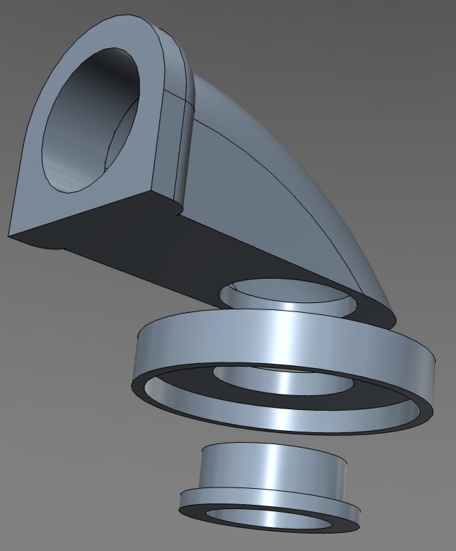


I'm making progress on my damper build. Working well so far.
https://www.youtube.com/watch?v=6FdGOQ3zvcU&feature=youtube_gdata_player
Ralph, you are intermixing sci-fi universes. This is unacceptable!
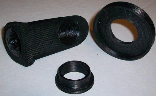
Has anyone tried printing one of these in PLA?
If you are a HMv4.0 (or older) owner you do not have a CAT5 jack or a proper servo jack (or even header) on your unit. I modified my case to fit a CAT5 jack and wired it directly to the board to connect the servo the blower and 2 probes. I had asked for a CAT5 or phone jack to be added to the HM V4.1 board, Bryan was reluctant at first, eventually he came around and did include a CAT5 jack option for the I/O on the HMv4.1 board, so if you have a HMv4.1 board you're all set. Tom did create a version of the HMv4.0 case that included a slot to mount the "aftermarket" CAT5 jack as well. Below is an edited re-post from when I added the CAT5 jack to my HMv4.0 board/case, I thought it might be useful to some so I am posting it here in this thread...
The way I setup this CAT5 jack it is not "mounted" to the case, so If I need to remove the HM board(s) from the case for any reason the CAT5 jack will come right out with it, no problem... it was pretty easy to do with a hack saw blade and some super glue (to mount the plastic for the latch). FYI, I am using the case for the larger 4-line display, which I believe is a tiny bit larger than the case for the standard 2-line display. I am not 100% sure it will work the same in the smaller case, because I haven't done it, but I have looked at it and I am reasonably sure it should work out the same
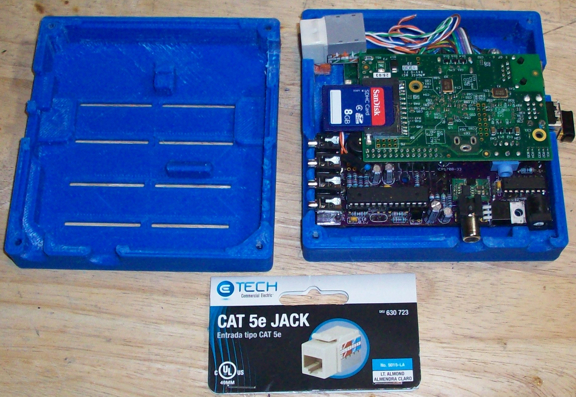
I opened up my case and shot some pics of the inside today in case anyone was interested in doing it themselves. I got the CAT5 jack from Home Depot (you can see the label in the picture), it is the type where you just punch down the wires and it snaps into a standard wall plate. I inspected the wall plate at the store to get an idea how to make a mount for it, I didn't end up mounting it exactly the same as the wall plate in the end. I just made sure the hole was tight to the jack on all sides and used the latch to prevent forward and backward motion. One piece of plastic glued in was all it needed, I used a piece that had an L-shape cause it was easier to position while gluing (and I had scraps handy), but you could actually use the piece of plastic you cut from the case glued in place to do the same job. (BTW, I just cut straight down with a hack saw blade on both sides then snapped the plastic out with some pliers. I cut down about 6mm on the top and 10mm on the bottom. The cuts need to be about 15mm apart)
Here are the pics:
And here is a pic showing the piece of plastic I glued inside for the latch. I used an orange plastic scrap so it would be easy to see what I added...
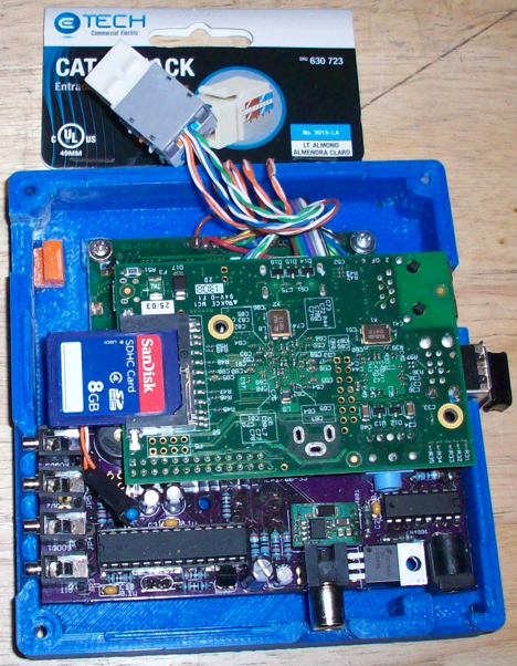
...and a pic of the whole thing assembled to make this post more comprehensive...
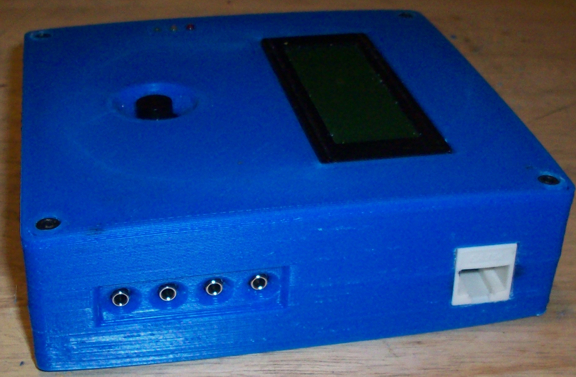
The CAT5 jack would have fit on either side, I chose the same side where the probes connect so all the wires would be on the same side. The Home Depot Website shows the CAT5 jacks available in color(s), it would have been nice to have a blue jack but I didn't even think of that when I was brainstorming this at the time.....
Got one from Home Depot and it fits perfectly. It's not black, but it fits!