INTRODUCING: the "Roto Damper"


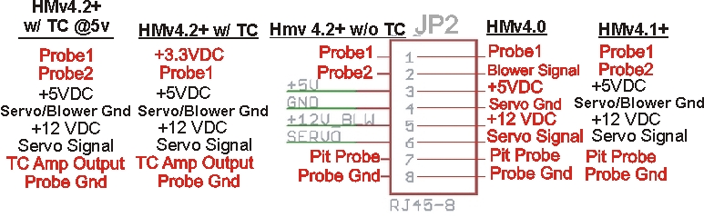
With the development of the RDTC amp board a new wiring scheme has become available, having the external TC amp running from the servo +5v power rather than running a dedicated 3.3v line just for the TC amp. This allows wiring the external TC Pit Probe and TWO food probes in addition to running the servo and blower over the CAT5 cable.

Here is the new CAT5 wiring chart, you must manually run jumper wires on your HM board for all items in RED:

HMv4.2.4_CAT5_Wiring.jpg


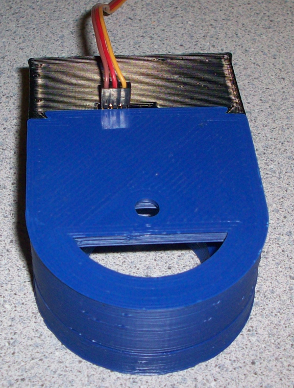
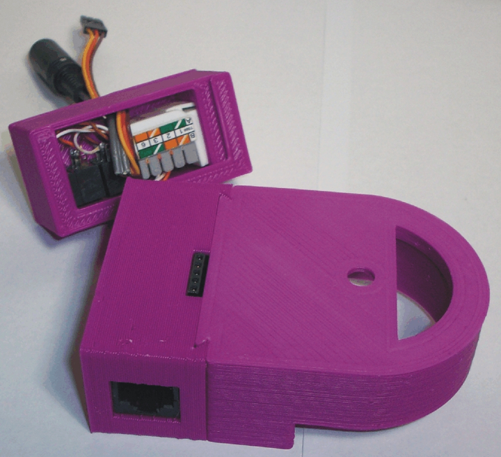
If you look at the CAT5 jack (from Home Depot) in the following picture, you will see numbers below each wire slot and what wire colors you should use when wiring the grill end CAT5 jack manually. (I always use the set of colors closest to the wires) Note the numbers are NOT 1,2,3,4 etc... Just punch down the wires following the numbers in the above chart based on your configuration....

RDv2i_PartsTCMated.jpg
 
Last edited:
Here is v5 of the RDTC I/O board John B and I have been working on... This one is very nice, if not for the holes on the header ending up the wrong size I would call it a done deal... I was able to drill out the holes and get a standard header installed, the board works great.

RDTCv5_Board.jpg

RDTCv5_Body.jpg

RDTCv5.jpg


This board as the REF Offset circuit perfected, the new single turn harsh environment ready Bourns Trim Pot works great, it can boost the TC from room temp up about 115F with single degree accuracy. The next and hopefully final version of the board is in the OSHPark pipeline already, the circuitry is the same but some stuff has been rearranged to accommodate a header with a friction locking back plate and this time the holes should be the right size. That's still a couple weeks off I would guess....
 
Recently while adding the thermocouple jack to my roto damper I experimented with using a shared ground for the servo, blower and probes cause I thought perhaps the RC filters on the probe lines would clean up any noise. Unfortunately I turned out to be wrong on that, with the shared ground the probe readings would jump around quite a bit when the servo moved and blower kicked in, must be current rushes going through that ground wire freaking out the ATMega.
So I went back to a dedicated ground for the probes and everything has been running smooth as silk over my 50"+ CAT5 cable again. In order to use the thermocouple over the CAT5 cable the thermocouple needs to be on the roto damper end, if you send the raw thermocouple output down the CAT5 cable there is a large temp offset that varies with the ambient temperature, with TC plugged directly into the amp (on the roto damper end) I don't have this problem.
Here is an updated diagram of suggested wiring for the CAT5 jack for HMv4.0-4.2 with probes and/or thermocouple:
HMv4.2.4_CAT5_Wiring.jpg

Hello. I see in later posts that you are working on adding a T/C amp to the RD. Cool improvement.

In my past engineering experience, I used to run a big lab with temperature data acquisition equipment. We used T/C extension cable - sometimes 100 feet long. The cable can be purchased from places like Omega. It has the correct metal conductors for the T/C type - thus minimizing effects of the additional connections.

Have you checked into doing that? Of course, it would require a T/C cable that is the same length as the CAT5.
 
Not really an option to run a 50FT TC cable, the cost of that would be huge, let alone the PITA running that cable along side the CAT5 cable. And why bother, with the TC amp at the RD the TC works just fine over the CAT5 cable. Cost wise I'm pretty sure the RDTC board will be much cheaper than a long length of type K TC cable. In addition to this, manually wiring the CAT5 jack and standard probe jacks in the RD (original old school method) can be a little frustrating, though I have it down now the first time around for home builders could be a PITA. With the RDTC board it takes about 5 seconds to pop the board into the RD body, DONE DEAL, CAT5 jack TC amp and 2 probe jacks in place and ready to go...
 
Not really an option to run a 50FT TC cable, the cost of that would be huge, let alone the PITA running that cable along side the CAT5 cable. And why bother, with the TC amp at the RD the TC works just fine over the CAT5 cable. Cost wise I'm pretty sure the RDTC board will be much cheaper than a long length of type K TC cable. In addition to this, manually wiring the CAT5 jack and standard probe jacks in the RD (original old school method) can be a little frustrating, though I have it down now the first time around for home builders could be a PITA. With the RDTC board it takes about 5 seconds to pop the board into the RD body, DONE DEAL, CAT5 jack TC amp and 2 probe jacks in place and ready to go...

Thanks Ralph. That all makes good sense. I look forward to getting my parts from you so I can get my HM running on my cooker instead of on my test station.

I understand the T/C amp concept, but I am fuzzy on your REF offset circuit project. I will wait until I get my parts and get it going before asking any more about it.

Thanks again.
 
The REF offset circuit is completely optional, not needed for cooking and not even useful in warm climates.....
Here's the background on that. The TC circuit used in the HM will bottom out at around 37F, if the temp gets colder than 37 the HM will just stay at 37F. I live in the midwest were temps get cold so I wanted the TC to measure down below freezing. To do this you must offset the output of the TC amp with a reference voltage, which will artificially raise registered TC temp. Then you use the HM Config to apply a negative offset in the amount you have boosted the TC with the REF circuit. The low end operation range for the TC will then be extended down by the amount you have offset the TC. If you offset the TC by 50F, for example, the TC will now read down to -13F instead of 37F.
Most people wont want or need this, and many (lucky) people live in areas that don't even get down below 37F, so this would be of no use to them (unless they want to use their TC in the freezer!). Let me know if you would have any need for this, I have a couple prototype boards here, some with the offset circuit installed and some without...

Great description. From the previous reading I did, I was picturing that concept (electrically shift the T/C amp output, and compensate for it in software). Yes, that means I caught up - finished reading this entire thread.

I am game for that Ralph. Include it in my RD if you want to.

So the thermistor probes do not have the low temp limitation - just the T/C amp circuit? In other words, when starting a cook, if the meat is near freezing, the thermistor probes will indicate that temperature accurately?
 
It is the TC amp circuit itself that has the lower limit in this case. I am sure there is some limit to the standard probes in the HM, but I don't know what it is, Bryan could probably tell you that... Standard probes DO register down well below freezing without any special settings or mods.... Of coarse each individual probe has it's own operational temperature range as well...

I should note, however, with previous version of the HM (prior to HMv4.2) there were no RC filters in place on the probes. Due to this and poor layout which allowed a lot of electrical crosstalk on the board, probes would often drop offline even at room temperatures (specially Maverick 732's). The HMv4.2 runs MUCH cleaner due to better layout and the added filters, running my roto damper with the RDTC board over a ~50ft Cat5 cable I was unfortunately able to read temperatures down below 0F on both the TC and my Thermoworks Pro probes. That said, if for any reason your HM is picking up unusual levels of noise (poor power supply/bad cables etc) you might see your probes drop off at higher temps...
 
The probe comparison tool will show you the response curves of the thermistor probes. HeaterMeter has a hard cutoff of -4F (-20C) after which any probe will read "Off". However depending on the noise levels, you may start bumping into the threshold before that.

Unless there is a reference voltage circuit, the thermocouple is restricted by how close the amplifier can pull the output to ground, which is somewhere around 35-37F.
 
With what we hope is the final version of the Roto-Damper Thermocouple I/O board (RDTCv6) on the way time has come for me to update my sliding back case a bit. Since you can only connect one Thermocouple Amp to the Pit Probe input on the ATMega at a time, when you connect the external RDTC amp to the Heater Meter you must disconnect the onboard TC amp and insert the output from the external amp in its place. Thats seems such a waste, not being able to use the TC amp you have onboard, so a while ago I drilled a hole in my case and installed a cheap radio shack toggle switch between the internal and external TC amps on my heater meter. It works great but its ugly and obtrusive with the toggle sticking out so far. So I sourced a panel mount rocker switch that fits in the case, BARELY, but fits... Here are a few pics:

HMv4.2CaseSwitchBlue.jpg

HMv4.2CaseSwitchInside.jpg


I think it worked out nice! There is actually room for two switches there if the need were ever to arrive.

You can't see it well in the pic, but what I have done is omit the 100K resistor on the HM board for the Thermocouple (the one that kinda sits between the TC jack solder lugs) and installed a two pin header there instead. Two left over pins from the LCD header work perfect. Then you plug in a two wire connector to this header, one wire has the output of the onboard TC amp, the other wire is the Pit Probe Input to the ATMega. You then install the 100K resistor (that you omitted from the HM board) on the COMMON leg of the switch and connect the lead that goes to the Pit Probe Input to the other end of the 100K resistor (this puts the 100K resistor in series with the output of the switch). You connect the other wire from the onboard TC amp output to one of the remaining legs of the switch and the output from the RDTC amp on the other leg. This way the switch will select which TC amp to use and put the 100K resistor in place on whichever TC amp is selected by the switch.... and you can disconnect it easily to remove the boards from the case.

Another scenario to make use of the onboard TC amp, if you were for some reason needing to use two thermocouples you could jumper over the onboard TC amp to Food Probe 1 input and put the switch on the 10K pullup resistor for Food Probe 1 so you can use the onboard TC amp in that slot.
 
Last edited:
On the B+ board i added a 4 pin wire header, along the edge next to the cat5 jack for the unused connections. Then I added a two pin header,one side connected to the 100k resisterand the other connected to the onboard amp. So, if not using a offboard tc you would need to jumper the pads together. Or if you decide to add a off board tc, it give you a plce to wire some wire for a switch.
 
Love the header for the spare CAT5 pins, been wanting something, at least non-drilled solder pads, for quite a while now... because the pins on the CAT5 header are a tad close to piggy back solder wires too. With thin solid wire you are ok (like telephone wire), but with thicker or stranded wire it would be kinda tough.

The other jumper for the TC amp is nice too.. but oddly enough the holes for the standing resistors by the probe jacks mate with the spare pins from the LCD header perfectly. If those resistors were laid down that would't have happened, happy coincidence I guess... Since you have to remove the 100K resistor from the board to install the header you need to put it in place on the switch, which is simple and convenient, works out nice...
 
Last edited:
I have been using what they call, "wrapping wire" It fits in the cat5 holes nicely, but you need to hot glue them, as they are easily broken, and they are a pain to strip the 30 gauge wire.
 
Yah, I generally use the wire from a CAT5 cable, the solid wire type. The wire itself is pretty similar to the old school land line phone wire. It is slightly delicate but I don't hot glue or anything... Having holes to install a header or direct wire to the board is great. Perhaps you should put a double row header with the CAT5 pins on one side and leads that go to the switch legs of the probe jacks on the other (and one to ground), so you could use the spare CAT5 wires as you wish, or jumper them over to the probe jacks either with wire or install headers and use jumpers like you would see on a motherboard...
 
If you have an old IDE cable lying around you can cut the strands apart near the ends (I used a razor blade). Then, you strip them and tin the wire strands with your soldering iron to make them fit in small holes without fraying. I used this method when doing the 4-line LCD mount and it worked real good. The stranded wires make them pretty flexible as compared to cat5 wire (solid core).
 
I don't put the wires into the holes along side the CAT5 jack pins, I just tin the (solid) wire and then heat the CAT5 pin(s) solder joint and melt the wire in making sure solder flows and then hold in place until it cools...
 
I now have all of the RDTC parts from Ralph. They look real good.

Last night I finished modifying my HM4.2: added jumpers to connect the unused CAT-5 pins to the food probe jacks. Also modified the T/C circuit to use the rocker "selector" switch. The HM works like it should - with the T/C, servo and blower connected to the HM.

Tonight I will try to assemble the RDTC and test it with T/C, food probes, servo, and blower connected to it.

I am planning on having my first real cook Wed night / Thursday. Of course, the forecast includes rain.

How much do I need to protect the RDTC from rain? I may not be able to have everything under cover.
 
I leave my RD out exposed to the rain and snow, only issue would be if it gets rained on and then frozen you might have to manually give it a twist to break the ice between the RD barrel and body. It's obviously best not to get things wet, specially the wiring, but don't stress over it, it will run right through the rain....


Back
Top