INTRODUCING: the "Roto Damper"


Yeah, you can remove the scissor pins and solder wires directly to the pcb or if you have multiple wires just put bare wires into the scissor pin and solder them to that.

The fit is tights and snaps in. I had to use a cat5 cable to pull on to get it all the way in.
 
I got my TC reference voltage board done tonight, worked out really well.
Since the OP777 Op Amp is SMD I decided to build it up on one of the SMD to Through Hole adaptor boards I have laying around. I mapped out the circuit according to the pinout of the OP777 then soldered it to the board and used that as a platform to build on. Soldered the SMD 1M (5-Turn) pot to the board on the +3.3v pin and a NC pin (to give it a more solid mount, Pin 7-8), added the (through hole) 0.1uF cap (using another NC hole to give it a solid mount as well, pin 4-5) then used jumper wires to make the rest of the connections. Here is a pic of the board next to the schematic and circuit diagram:
TC_Ref_Driver.jpg


The circuit works really well. I tested it at first with a 12V wall wart that was reading almost 18VDC with no load on it (believe it or not). I was able to slowly sweep the output voltage from 0 to 18v with a very fine adjustment and the voltage was very stable.

Next I went to connect it to the HMv4.1 TC amp, which is where the process gets a bit more hairy. Pin 2 is the REF pin, on the circuit board pin 2 is shorted to Pin3 (GND), so you have to cut that trace between the tiny SMD TC chip legs. With Magnifier visor I was able to cut that trace easier than expected with a regular razor blade. Tested with the MultiMeter and the legs are indeed isolated, with the REF pin isolated the TC amp is no longer registering on the HM (as expected). Now the hard part, I need to connect a wire from the output of the REF Amp to the tiny leg of the TC amp (Pin2). It seemed an impossible task, and doomed to come loose even if I manage to get it done, so I wrapped the wire through the hole on the board to give it some support. Second try soldering and I actually got it, seems stable and the TC registers now so GREAT!

When I turn the pot all the way in the REF pin is connected to GND, as in the standard TC amp circuit, at this point the TC reads the exact same temp as when I use the TC amp on my HM board, so all good. As I turn out the pot the TC temp starts to rise, the adjustment is fine enough so I can raise it up in 1-2F steps, PERFECT! Here is a graph of my HM while I am adjusting the offset pot:
TC-Offset.jpg

I do some fine adjustment, then some rapid adjustment up to about 200f, then dial in the offset to 60F, and I will use an offset of -60F on my HM config for the TC. Since my TC was bottoming out at 37F before the -60F offset I am expecting it will now bottom out at around -23F if all things hold true. Now I can see how miserably cold it gets here this winter! LOL
 
Last edited:
My wife, who is experiencing her first winter here, can tell you "It's COLD" lol. But, that wont help ya though, as anything below 70 is cold to her.
 
I love the application! Let me ask you, Ralph, two years ago did you think you'd be designing electronic circuits to solve technical challenges? Looks like it works perfectly too.

I don't want to wish this on you, but I hope it gets really really cold there soon so we can see it work!
 
It got down to about 11F last night, TC read just fine down that low (rather than bottoming out at 37F) so that's confirmation it is working as planned.
Two years ago I had no idea my grill would be on the internet, that's for sure! LOL Though I have been working with electronics in some form or another for most of my life, doing lots of repair, I've designed a few tube guitar amps, a custom power soaker circuit to artificially provide a reactive load for the amp without a speaker, and other miscellaneous Solid State design here and there when I've found a need, so I've done a bit of electronic design over the years when I am inspired by a project.... So that part doesn't surprise me. The HM surprised me, a very ingenious invention that captured my imagination and inspired me to dig in and make it do what "I" want it to... So hats off to you for inspiration!
 
I did a "low and slow" last night with the TC running with the REF offset and I am glad to report all is good. I tracked the TC temp along side a Thermoworks Pro probe for reference and the TC is reading accurately from below freezing up to the mid 200's (I ran the pit at 225).

I also re-wired my HM and RD while working on the TC REF mod, running the TC and REF modules on the 5V wire for the servo which allowed me to wire up a second standard probe through the RD. Although it works and is accurate I am seeing the noise indicator pop up on the TC when the servo is moving. It's not too bad, though the noise indicator pops up fairly often the TC still remains fairly stable, only fluctuating less than 0.5F at most, it generally bounces around about +/-0.3F. The small fluctuation didn't have too much of an effect on the HM operation, the servo wasn't over active and the pit was stable. That said, I got really used to having my TC rock solid with no fluctuation in temps, seeing that little yellow resistor looking noise indicator just bothers me. So I think sooner than later I will either rewire the HM and RD to run the TC on 3.3v again, or I may possibly experiment with regulating down the 12v or 5v in the RD to power the TC amp, or perhaps adding a capacitor on the +5v line in the RD to see if that filters out the noise from the servo movement.
 
I had a setback in the RD thermocouple. I set it up on my UDS today and I saw the noise 5 indication, but the temp was slowly dropping to set point(230) and then it went below. it stayed below for a bit and started to climb and it went over 300. I knew something was wrong, so I plugged in the TC on the HM and it dropped to below 200.

Afterwards, I took the thing apart again, and did some resoldering and exchanged some parts and I was able to get a very stable reading, regardless if the blow and servo are running. I don't see a change. I currently have it up and running with the TC in a light bulb, which has a stable 180 degree temperature. The temperature on the TC has barely moved from between 180 and 182.

Is there a way to get more of the TC PCB boards made, I don't like the Adafruit ones and I just had the one of the TC boards from the older 4.1 boards. I would like to order a few from OSH. I used to be able to get around in Eagle but I have not used in a while and im really rusty.
 
Is there a way to get more of the TC PCB boards made, I don't like the Adafruit ones and I just had the one of the TC boards from the older 4.1 boards. I would like to order a few from OSH. I used to be able to get around in Eagle but I have not used in a while and im really rusty.

John, If you are able to find how to have these boards made please let us know. Now that the cold weather has arrived here in Chicago the thought of just running a cable out to the smoker is sounding real good right now. Thanks, Dan
 
John, If you are able to find how to have these boards made please let us know. Now that the cold weather has arrived here in Chicago the thought of just running a cable out to the smoker is sounding real good right now. Thanks, Dan

It would not be to hard to use Eagle to make up a board with the 4.2.4 thermocouple components. I have not had the time to dive into eagle yet. Bryan may be able to work up a stand alone thermocouple board.....if he reads this...... hint........hint......lol.
 
I had thought of doing an I/O board with a TC amp for the roto damper... I had no problem working out the schematic in EAGLE but had a hard time translating that over to the board layout. The learning curve on that end seemed a bit steep and I wasn't sure if there would be enough interest for me to invest my time in figuring it out. Maybe I will give it another go now that winter is upon us here in the Midwest...
 
I had thought of doing an I/O board with a TC amp for the roto damper... I had no problem working out the schematic in EAGLE but had a hard time translating that over to the board layout. The learning curve on that end seemed a bit steep and I wasn't sure if there would be enough interest for me to invest my time in figuring it out. Maybe I will give it another go now that winter is upon us here in the Midwest...
Thats the same problem i have with eagle, i have made button boards for the heatermeter in prior versions. But those were homemade pcbs and on a larger scale. I never worked with smd parts before. I do have an idea of combining the cat5 and thermo amp into one unit that would eliminate wires except to the probe jacks.
 
Hi Ralph have you been able to check your email lately as if possible i would like to get a copy of the Roto Damper STL's

Thanks

Davey
 
I've been asked a couple times about the mods I did to the little thermocouple amp board that came with the HMv4.1 to make it work as an external TC amp, so I decided to repost the info in this thread for reference....
-----------------------------------------------------------------------

Today I finally got a chance to dig in and examine the little thermocouple board that came with my HMv4.1 board. Although this was an unsuccessful prototype thermocouple amp, the circuit structure is pretty similar to the working thermocouple amp that is found on the HMv4.2 boards. Their are quite a few component value changes, and two additional resistors added to the HMv4.2 circuit.

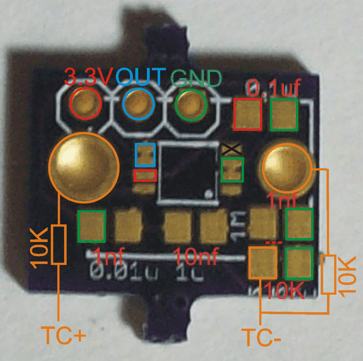
I found the easiest way to modify this board to match the new circuit was to first cut the trace between the 1nf cap and the 10K resistor (where the red dotted line is in the picture below). You have to ignore the component values silk screened on the board and install the values I have added in the pic (values from the HMv4.2.3 circuit*) then add the two extra resistors shown. I chose to use through hole resistors because I found that to be easier. I built and tested this circuit tonight and it is working great.

*Bryan noted that he has changed the SMD 10K resistor shown in the diagram to 1K on the HMv4.2.4, however, I am running the 10K and it is working great. Either value should work fine, this value can be adjusted depending on how much noise you may be picking up on the TC line. I am running the TC amp output through a 50+ft CAT5 cable with the 10K resistor and I've got no noise whatsoever, I never see the noise symbol appear during normal operation and the TC graph is always nice and stable.

Here is a pic of the HMv4.1 thermocouple amp board with the above modifications detailed:
HMv4.1_to_HMv4.2_ThermocoupleAmp.jpg

Note the black X on Pin4 of the thermocouple amp, that pin is not used so you don't have to worry about soldering it. Also note that Pin2-3 are bridged (and are gnd), and Pin5-6 are bridged as well (this is the output), so you don't have to worry about clean solder between those pairs of legs on the IC

Do you think this will work?

 
Because the TC amp pads are all trashed below.

Also, I think I need to put the out ( white ) on the right side of the 1K resistor on the TC- jack.
 
Well, if the pads on the TC amp below are all trashed then they could be shorted out or leaving additional components in the circuit that shouldn't be there... So you might want to cut the trace on the TC Amp side of the resistors on the HM board you plan to use to isolate them from the mess.. Also, this HM v4.1 TC amp board circuit is a bit different, you need to cut the trace like where the dotted line is and install the components in the orientation shown on the image. You would have to dig in and figure out if you can skip making that mod and use the parts on the HM board instead in that region... the two resistors on the TC jack should be easy enough to isolate and use though.
 
Last edited:
Here's a couple pics of my recent experiments in damperland...
HiFlowDampers.jpg

HiFlowDampers2.jpg


The idea was to make a more compact damper with higher flow... This experiment has been the second most successful damper next to the Roto Damper. As you can see from the pictures, this design has the output of the blower shooting straight through the output tube completely unrestricted or deflected, so you get full on blower output shooting right into the grill, it also has a much larger opening on the valve. Additional benefits of this design is the blower and servo are completely inclosed, and completely stationary, so no more moving wires and external blower. The negative side to that is that wires have to poke out through the sealed regions of the valve which will inherently introduce leakage. In spite of this the valve does seal very well and had no problem choking down the pit during overshoot. The roto damper valve still reigns supreme because my goal with that design was to make the valve as tight as possible, which is why the servo and blower are located on the outside of the sealed area of the valve on the roto damper. The output of this damper is on the side so I went with square output instead of round but designed it in a similar manner as the RD, it mates to the grill through a customizable output cap that can accommodate the same types of connections as the RD... in fact I am using an output cap right now that mates to my existing RD output cap so I can swap back and forth between this new damper and the RD easily. The larger purple damper is pictured with an output cap to fit the BBQ Guru adapters or a 1" conduit connector, the smaller damper has an output cap made to mate with a RD output cap. The entire unit is designed for press-fit, there are no screws, glue etc required for assembly.

The more direct output from the blower to grill and larger valve opening does result in a more responsive damper, but that's a double edge sword... The damper was so responsive that I found the HM required very precise PID tuning to nail a steady low and slow temperature, though the fluctuations were small (and perhaps I am hypersensitive to it), it was a bit more difficult to tune the HM to this damper. On the other side of that coin, this damper will do a much better job nailing high heat cooks for pizza, steak etc due to the increased air flow.

Another negative to this design is it is very large due to having the blower inclosed in the unit. Unfortunately since the blower is encased in the unit these dampers can only be used with the specific blower it was designed around, so these dampers can not accommodate custom blowers like the RD can. The purple damper in the picture is made to fit the stock HM blower (pictured between the two damper), this damper came out quite large. I had another blower here that is quite a bit smaller but has nearly the same specs as the stock HM blower, this smaller blower has just slightly higher flow rate and a bit more static pressure than the stock blower. After holding the monster damper in my hand for the stock blower I decided to try a build around the smaller blower. The smaller build is real nice, barely bigger around than the RD and much shorter. Personally I think the full size unit with the stock HM blower is too big to work with... The smaller blower is a Delta BFB0512VHD, I got it at Digikey, and I think Bryan should maybe look at this blower as a potential new standard blower... Same/slightly better specs, similar price, similar output area, smaller overall size...

So, bottom line, I would call this a successful damper, in the smaller size with the smaller blower. The Roto Damper still reigns supreme IMHO for low and slow cooking because the valve seals better, and the path air takes through the RD makes the flow a bit more sluggish which makes PID tuning on the HM much easier. I find my Roto Damper will work great under a very wide range of PID parameters while this new higher flow damper was much more picky about PID settings.
 
Last edited:
Oh course you find a possibly better blower a day after I ordered 100 of the other ones. The smaller blower is a dollar more expensive though. I probably won't have to make another digikey order for at least a month but I'll grab one of the smaller blowers to try.

Isn't the back of the blower not getting air though? They intake from both sides, not just the top. How high can you get your temps with the new design without having to open the bottom vent extra?
 
Bryan, yes the fan is flat against the bottom of the case, I could make a stand off for the the bottom to let it breathe but I thought I would try this way first because that would add some thickness to the unit. As is this damper blows air like crazy, WAY too much for my kamado, so I have to throttle it back. So I see no reason to thicken up the design to allow air under the bottom of the blower, it's pulling plenty of air just from the top.... and Tom, I had this blower on my 3D printer as my "bridge blower" that kicks on to help the printer make longer bridges. I kinda chose it by size cause I didn't have much room to fit it in and never really had the HM in mind for it... but after I put a box around the stock HM blower and saw how large it was I started looking around and saw this smaller blower on my printer, looked up specs and when I saw they were a near match I decided to give it a go.... and go it does, this is a decent little blower...
 
Last edited:


Back
Top