INTRODUCING: the "Roto Damper"


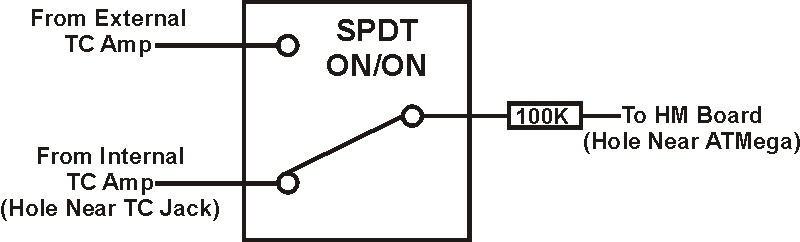
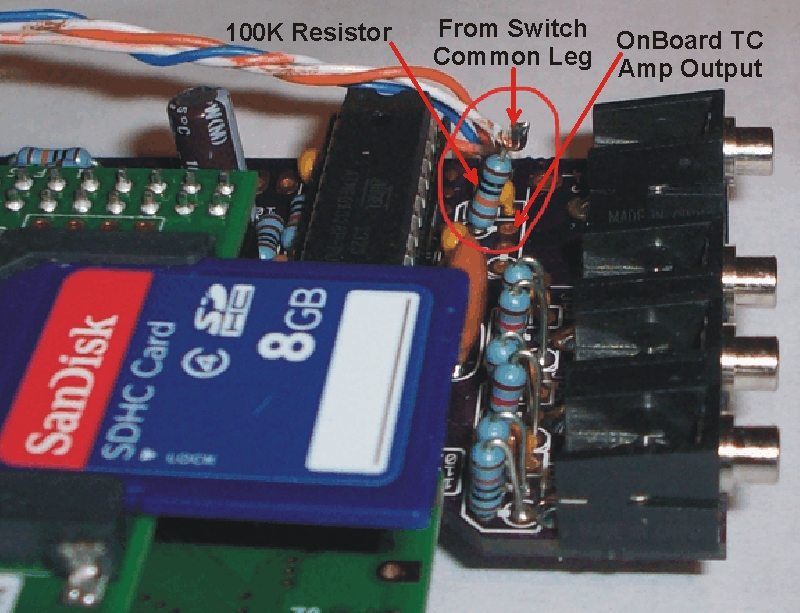
One side note, I have noticed when you lift that resistor if you do not connect an external TC amp to that resistor (or have one connected that is not powered) the HM will initially look like a TC is connected, but the reported temp will rise and rise at a fairly rapid rate up to about 1000F and then will report "No Pit Probe". As soon as you connect a TC amp (or power the amp that is connected) the TC will start to register properly.

I also get that but the temp goes up to about 350. I ordered an Adafruit breakout board to try. Since, I suspect my soldering of the TC board may be the problem. I will play with it some more
 
yeah, I have it lifted one side. I thought you have not had a TC on the HM when you have had a TC board in your Damper. I thought you said that you have a pit probe jack connected.

Some reason im still getting interference with the onboard TC when I try to use the TC in the Rotodamper.

Anyways, it could also be my soldering of the TC board itself so I'm going to try a Adafruit board, to see if it helps

I also Tried using the 5v and no difference, lol. but I as Bryan said it does work though.

Well, I think Bryan said theoretically when powered by 5V the TC amp will exceed the rated voltage for the ATMega but MIGHT work....

You might try soldering in a resistor leg or wire into the hole where you lifted the 100K resistor then tap it to the lifted resistor while the CAT5 plug is disconnected. At this point the onboard TC amp is in circuit (alone) and if you plug a TC into the onboard connector your TC should work normally. If this goes well then you need to look at the external TC amp you made closer for errors, and check the wiring you made from the CAT5 jack on the HM board, the pins are pretty close together and it is easy to make a solder bridge there, and also easy to think you have the wires tacked firmly in place when really they are not. You can eliminate the CAT5 wires from the circuit for testing, remove the jumper from the CAT5 jack to that resistor and connect the output of the external amp directly to that resistor, and tack the external amp to gnd and 3.3v of coarse.... If this works then you need to examine the connections at the CAT5 jack on the HM board, and also look at where you are stealing the 3.3v and ground from. I am grabbing the 3.3v from the power pin on the ATMega and I have used a ground from the probe ground and also have used a ground directly from the power jack, both seem to work equally as well. You might also check your CAT5 cable to make sure it isn't faulty, and make sure you have the wires punched down properly on the RD CAT5 jack, make sure you are using the probe ground in the CAT5 wire for the TC amp (not the ground for the servo and blower) and make sure the external TC amp isn't sitting up against anything that might effect it's readings.

On the external TC amp board itself, look at the color code on my diagram and check continuity between pads I have marked with similar colors to verify the circuit is proper.
 
Last edited:
I use a continuity checker religiously to double check before and after soldering something. the one thing I did not check, well I checked one of the 3 I bought from American Scientific, were the slide switches. Maybe the one I am using does not full turn off the connection to the wire that I connected to the spot of the pulled up resistor. I will go down and check in a few
 
Yah, definately eliminate the switch first before you dig into any of the other things... I have never used the switch myself, but in theory a switch is a switch and should isolate the non-connected leg when in the other position and therefore just work.....

One other thing that came to mind, which I am not SURE of... I am not sure if Bryan only made ONE iteration of this small TC amp board or if perhaps it went through an evolution, in which case your TC board could be slightly different? I am pretty sure it was a one shot deal, but the possibility that there were more than one design did come to mind... To my recollection there was only one, but Bryan may recall off there was more than one version? It did strike me as odd that your new TC- pad was not isolated after you cut that trace.....
 
I made some progress, but im more confused then ever lol

I had to move the resister from where I think you have it on your HM to the other side. Once I do that and change the wiring on the switch, I am able to get a stable temp on the RD thermocouple, but now its screwed up on the HM board when I plug in a Thermocouple.

So, I have a working TC amp on the RD and I have a working TC amp on the HM but I cant get both to play nicely with a switch for some odd reason which I will need to figure out why.
 
The hole for the resistor that is closest to the ATMega has a trace that connects directly to the top pin of the ATMEGA and also has the capacitor for the RC filter connected to it (but that's it for connections on that trace), so you need to have the resistor soldered to that hole (closest to the ATMega), not the other one...

I would recommend that you test both TC amps, one at a time, wired directly to the resistor (while lifted as described above), after you have both TC amps verified working properly then go about messing with the switch.

...and to be clear, when you connect the onboard TC amp to the lifted resistor, you take a wire from the hole where the resistor was removed and connect it to the end of the resistor that has been lifted.
 
Last edited:
Maybe you are wiring the switch wrong?

Here is a diagram for a SPDT switch:
SPDT-Switch.svg


You need to connect the resistor to the COM leg, and the TC amps to L1 and L2....
 
Maybe you are wiring the switch wrong?

Here is a diagram for a SPDT switch:
SPDT-Switch.svg


You need to connect the resistor to the COM leg, and the TC amps to L1 and L2....

Yeah that's the way I had it, I just used a continuity checker on the switch, maybe there is something else going on inside, so when I get home going to check into it further.
 
I fixed it, well I solved it seems to work good. I'll draw a diagram in a bit. I needed two 100k resistors attached to the HM and the attached to the middle connector of the switch. Then on the HM tc I had to connect its wire to bypass one of the resistors and on the side is connected to the tc on the rd. I don't get any stray readings of 300+, but only about 10°,then it slowly goes down to the correct temp of room temperature.

Thanks Ralph for all the help, Much appreciated.
 
Last edited:
I made temporary connections so they don't look good lol. The red/yellow wire is connected to the blob of solder in front of the switch and the two resisters are connected to the middle connection on the switch on the back of the switch. The picture makes it look like the yellow wire and resister are connected together but aren't. the white wire bypasses one resister.

Edit
Fixed issue
 
Last edited:
Doesn't make much sense to me, should only need the one resistor, but if it works for you that's all that counts.
I have used the method that I described to connect the onboard TC amp, and then the external TC amp, through the one resistor and both work fine... I really can't see a reason why a SPDT switch between the two of them wouldn't work just as if I were manually switching the wires, but I haven't actually done it, I am like 99% sure it should work as I expect....
Right now I have my HM in a all standard probe case, but I will print up a TC case and install the TC jack onboard with a switch wired the way I describe and report back the results sometime soon, gotta dig up a small switch first, know I got one around here somewhere....
 
I just got around to testing the TC switch on my HM and had no problem at all wiring it up as I described earlier (using just the one resistor). It is a rather simple thing, and worked as expected, but I made a diagram to make sure it is completely clear:

TC_Switch.jpg


As you can see in the diagram, the output from both the internal and external TC amps goes to the two switched legs, and the Common (usually center) lug of the switch goes to the 100K resistor (from the RC filter). This resistor is lifted from it's hole nearest the TC jack (remains soldered into the hole nearest the ATMega) and the switch Common leg connects to the lifted end of the resistor. The External TC Amp output would be a wire jumpered over from the CAT5 jack, and the Internal TC Amp would be a wire coming from the empty hole that you lifted the resistor out of (nearest the TC Jack).

Here is the picture again showing where the resistor needs to be soldered to the HM board:
TC_Insert.jpg


With the TC connected to the Onboard amp and reading accurate room temp, when I flip the switch I get "No Pit Probe", after moving the TC over to the RD (External Amp) the HM now reads the exact same temp it was reading from the Onboard Amp. If I plug a TC into both amps when I flip the switch back and forth the HM displays the selected TC temp perfectly without a glitch...

John, I don't know exactly what is going on that it didn't work that way for you, perhaps your switch is not a regular SPDT or something? (I am using one I bought from Radio Shack today) Or maybe you didn't connect the 100K resistor to the Common switch leg, or didn't solder the resistor to the right hole on the HM board? IDK All I know is the above switching works. The way you have the two resistors connected doesn't make much sense to me, and actually connects the output from the two TC amps together (although with 100K resistance between them), I don't think that is the best thing to do, specially when the above detailed switching works flawlessly.
 
Last edited:
Thanks for giving it a try. Im still not sure why I had problems. But, Im going to rewire everything and clean it up before putting it all together this weekend. At least, I know 5v works fine and I can get rid of the 3.3v on the cat5 and add another probe.
 
I've done some preliminary experimentation running the external TC Amp from various voltages and have mixed results....

Running at 3.3v from the HM board the internal and external TC Amps read exactly the same, movement of the servo and running the blower has no effect on the temp readings.

Running at 5V from the HM board the External TC reads 1-2 degrees higher than the internal TC, movement of the servo and running the blower has no effect on the temp readings.

Running at 12V (12-15V, unregulated PS output) the external TC jumps up about 5 degrees, movement of the servo has no effect, however the External TC jumps up another 2-3 degrees when the blower kicks on. I am using a cheapo PS, with the blower off the output measures 15.9V, when the blower kicks on it drops to 14.5V.

I also attempted to use a separate regulator for the External TC power. At first I tried using the 3.3v reg used in the HM. Powered by the 12V line it smoked immediately, at which point I checked it's operating voltage, which is 6v Max... DOH! Next I tried the OKI DC-DC regulator, which made a nice stable 5V whether the blower was on or off... The External TC behaved similar to when powered by the onboard 5V regulator, except while using the external 5V regulator the External TC now jumps up 1-2 degrees when the blower kicks on. (which is surprising to me but I am just reporting the facts!)

These experiments were all done at room temp of about 67F, I am not sure if the temps will move the same amounts or more/less when the TC is reading higher grilling range temps, next stop is a hot water test to see how it responds in that range.

So far this seems to indicate if you want the absolute cleanest signal from your External TC it is best to power it with the same 3.3v that powers the onboard TC amp and ATMega. The stated offset is not much (at room temp), but the fluctuation of the TC reading when the blower comes on is a big deal, because the HM will react to it and cause the blower speed to bounce around because it thinks the temps are changing rapidly. Ideally you want the pit probe to be unaffected by the servo moving and blower blowing to get the smoothest HM operation...

I will be continuing these experiments over the next day or so and will report back further results....
 
Ralph, thanks for all your help. I redid the wiring and switch and all seems good now. I also tried an Adafruit breakout board tonight and found that it was about 4 degrees higher then the board I made. So that's not going to be used, lol. The only problem I see, so far, is the noise level is 7, but it seems very stable and accurate compared to the thermoworks I have connected to the HM, they all read about the same.

This link will be live until Friday night or so

uds.servebeer.com/luci

Oh, by the way I'm not a Chargers fan, lol.
 
Last edited:
With the Adafruit TC board I think there is a DC offset that you need to cut a trace or lift a leg and then ground before it works right with the HM... but I think the temp offset should be MUCH higher than that not done, so you probably did that already....
 
The only problem I see, so far, is the noise level is 7, but it seems very stable and accurate compared to the thermoworks I have connected to the HM, they all read about the same.

This link will be live until Friday night or so

uds.servebeer.com/luci

Oh, by the way I'm not a Chargers fan, lol.

You mention a noise level of 7, are you running the noise reporting firmware, where do you get that number? One thing I dig the most about the HMV4.2 is the RC filter that cleans up the noise, I NEVER see the noise indicator pop up on the TC (or any probe that is in good working order), even when running over a 50+ft CAT5 cable. Are you running two grounds through the CAT5? (one for the servo and blower, another for the probes and TC amp) My TC is SUPER STABLE, like flat line stable, not a blip to be seen.....

...and BTW, your link is not live at this time....
 
Not sure what's wrong with the link. It worked fine last night and I tried it this morning and I too could not get it to work.. Might be a no-ip issue, as I checked all ports and routing.

Anyways, its also very stable, all night its been 66°, so I'm not worried about the little noise icon. But will try a very long cat5 to make sure its still stable. I'm using the same connection you have used.

But, will switch to 5v, and do some testing, tonight and this weekend.
 
Yah, the longer the cable the more likely you'll pick up noise.... but I never see the noise icon, even over a 50ft CAT5 cable, so you could be doing even better... Perhaps you should experiment with the routing of the jumper wires you put in place between the CAT5 jack and the probes, 'cause they could pick up noise pretty easy. Also make sure they are soldered firmly to the pins on the CAT5 jack, since the solder joints are so close together and so small it is easy to get a crappy solder joint there and think you're done... The first time I used the CAT5 cable I went through all sort of changes trying to find the source of my noise issues, turned out to be a bad solder joint at the CAT5 jack....


Back
Top