RalphTrimble
TVWBB Diamond Member
I've been asked a couple times about the mods I did to the little thermocouple amp board that came with the HMv4.1 to make it work as an external TC amp, so I decided to repost the info in this thread for reference....
-----------------------------------------------------------------------
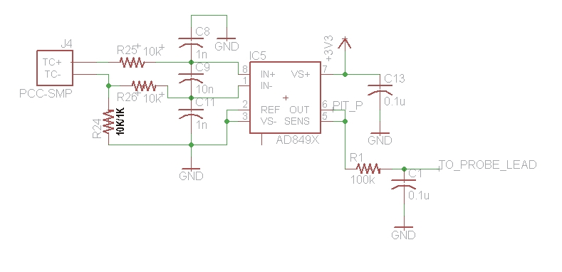
Today I finally got a chance to dig in and examine the little thermocouple board that came with my HMv4.1 board. Although this was an unsuccessful prototype thermocouple amp, the circuit structure is pretty similar to the working thermocouple amp that is found on the HMv4.2 boards. Their are quite a few component value changes, and two additional resistors added to the HMv4.2 circuit.
I found the easiest way to modify this board to match the new circuit was to first cut the trace between the 1nf cap and the 10K resistor (where the red dotted line is in the picture below). You have to ignore the component values silk screened on the board and install the values I have added in the pic (values from the HMv4.2.3 circuit*) then add the two extra resistors shown. I chose to use through hole resistors because I found that to be easier. I built and tested this circuit tonight and it is working great.
*Bryan noted that he has changed the SMD 10K resistor shown in the diagram to 1K on the HMv4.2.4, however, I am running the 10K and it is working great. Either value should work fine, this value can be adjusted depending on how much noise you may be picking up on the TC line. I am running the TC amp output through a 50+ft CAT5 cable with the 10K resistor and I've got no noise whatsoever, I never see the noise symbol appear during normal operation and the TC graph is always nice and stable.
Here is a pic of the HMv4.1 thermocouple amp board with the above modifications detailed:
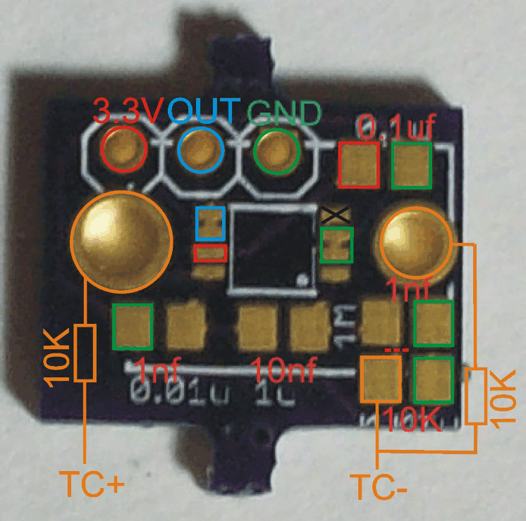
Note the black X on Pin4 of the thermocouple amp, that pin is not used so you don't have to worry about soldering it. Also note that Pin2-3 are bridged (and are gnd), and Pin5-6 are bridged as well (this is the output), so you don't have to worry about clean solder between those pairs of legs on the IC
And here is a pic of the actual board all built up:
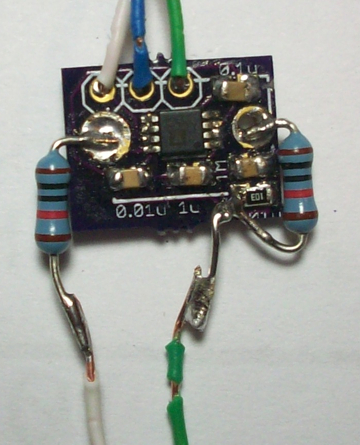
So this board could be modified and used as either an external thermocouple amp, which can run outside the HM and allow you to send the thermocouple output through the CAT5 cable with the blower and servo, or it can be used to add thermocouple pit probe support to pre v4.2 Heater Meters, or it could be used to add a second thermocouple input to a HMv4.2. I'm really happy how it worked out.....
To connect an external TC amp to the HM you should lift the end of the resistor in the RC filter for the Pit Probe and insert the output from the external TC amp there. Make sure you lift the end of the resistor that is toward the TC jack, not toward the ATMEGA, as this will leave the RC noise filter in place which is critical to get a clean signal from the TC.
Here is a pic of the resistor lifted with the external TC amp output inserted (through the white wire):
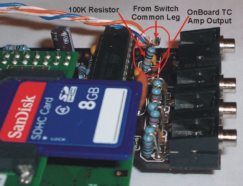
Note in the pic I have the standard probe jack installed (rather than the TC jack) because I am not using the on board TC amp. I installed the standard jack simply to test the fit of my sliding back case on an all standard probe HM build. You could install the TC jack and and use the on board TC amp in some capacity if you like. Either install a switch to toggle between internal/external TC amp going to the resistor shown (to use as pit probe), or you could also jumper the output of the onboard TC amp over to a food probe and use the onboard TC amp to add support for a second TC probe. Note that you must remove the pullup resistor for the probe you jumper the onboard TC amp to if you decide to go that route....
-----------------------------------------------------------------------
Today I finally got a chance to dig in and examine the little thermocouple board that came with my HMv4.1 board. Although this was an unsuccessful prototype thermocouple amp, the circuit structure is pretty similar to the working thermocouple amp that is found on the HMv4.2 boards. Their are quite a few component value changes, and two additional resistors added to the HMv4.2 circuit.
I found the easiest way to modify this board to match the new circuit was to first cut the trace between the 1nf cap and the 10K resistor (where the red dotted line is in the picture below). You have to ignore the component values silk screened on the board and install the values I have added in the pic (values from the HMv4.2.3 circuit*) then add the two extra resistors shown. I chose to use through hole resistors because I found that to be easier. I built and tested this circuit tonight and it is working great.
*Bryan noted that he has changed the SMD 10K resistor shown in the diagram to 1K on the HMv4.2.4, however, I am running the 10K and it is working great. Either value should work fine, this value can be adjusted depending on how much noise you may be picking up on the TC line. I am running the TC amp output through a 50+ft CAT5 cable with the 10K resistor and I've got no noise whatsoever, I never see the noise symbol appear during normal operation and the TC graph is always nice and stable.
Here is a pic of the HMv4.1 thermocouple amp board with the above modifications detailed:
Note the black X on Pin4 of the thermocouple amp, that pin is not used so you don't have to worry about soldering it. Also note that Pin2-3 are bridged (and are gnd), and Pin5-6 are bridged as well (this is the output), so you don't have to worry about clean solder between those pairs of legs on the IC
And here is a pic of the actual board all built up:
So this board could be modified and used as either an external thermocouple amp, which can run outside the HM and allow you to send the thermocouple output through the CAT5 cable with the blower and servo, or it can be used to add thermocouple pit probe support to pre v4.2 Heater Meters, or it could be used to add a second thermocouple input to a HMv4.2. I'm really happy how it worked out.....
To connect an external TC amp to the HM you should lift the end of the resistor in the RC filter for the Pit Probe and insert the output from the external TC amp there. Make sure you lift the end of the resistor that is toward the TC jack, not toward the ATMEGA, as this will leave the RC noise filter in place which is critical to get a clean signal from the TC.
Here is a pic of the resistor lifted with the external TC amp output inserted (through the white wire):
Note in the pic I have the standard probe jack installed (rather than the TC jack) because I am not using the on board TC amp. I installed the standard jack simply to test the fit of my sliding back case on an all standard probe HM build. You could install the TC jack and and use the on board TC amp in some capacity if you like. Either install a switch to toggle between internal/external TC amp going to the resistor shown (to use as pit probe), or you could also jumper the output of the onboard TC amp over to a food probe and use the onboard TC amp to add support for a second TC probe. Note that you must remove the pullup resistor for the probe you jumper the onboard TC amp to if you decide to go that route....
Last edited: