Bryan Mayland
TVWBB Hall of Fame
I think that's Ralph that has the sliding back case design but I don't think the files were ever posted. If you email him and he has them I'm sure he'd share rotodamper@hotmail.com or PM him here @RalphTrimble.
I'd love to see in a next version an option for a more robust power plug. For some reason my power supply has spotty - perhaps the center pin sizes don't match up on mine but there are screw in locking power pins and it would be ideal...
Yup, you have something thats not right.
Nothing wrong with Heatermeter power supply, it fits snug, holds tight , works great.
Try the one sold in heatermeter store
I second that, I have never had a problem with the power jack... I've used all sorts of random power adapters and find it works great with most of them, please do not change it!
Hi Bryan, thanks for the response. The readings I get are as follows:I know you said that you had 4.96V on the 5V line, but what's the voltage on the servo pin (at either the RJ45 jack or the far end). With a servo range set up in the configuration to be 1000 to 2000 with fully open at 100%, I get 0.390V at 0% output, and 0.630V at 100% output. The values will be different depending on how your multimeter handles a constantly changing voltage, but you should see a voltage difference on the signal pin when the output changes.
| @ Circuit Board Readings | @ RJ45 Readings | |
| Servo Signal -> | 4.98V (constant) | 4.92V (constant) |
| 5V Line -> | 5.01V (constant) | 4.96V (constant) |
| Fan at 0% | ||
| Servo Signal -> | 4.98V (constant) | 4.98V (constant) |
| 5V Line - | 5.01V (constant) | 5.01V (constant) |
")
Hi Bryan, checking the voltages as you mentioned above on Q5, I get 4.96V top left pin, 2.26V on the top right, and 3.3V on the bottom middle pin. I will replace it to see if that results in the voltages you've provided. One question, if I look at the troubleshooting voltages guide....on Q5 the voltages on the picture show Yellow=12V for top left pin, Green=?V for top right, and Pink=3.3V for middle pin. or am I reading this incorrectly? ThanksAh we're on to something there! Check at Q5 (one of the BS170s) it should be 0.390V on the top left pin, ~0.250V on the top right, and 3.3V on the bottom middle pin. Sounds like that part there might be blown and not transferring the servo signal.
Oh wow good catch. 3 years that image has been up there and I've never noticed that is wrong. The top left should not be yellow, it should be a green dot. Green dot just means "not specified" or "it depends". The voltages I've provided here I just measured from an active 4.3 device, and it on mine it was actually 0.390V (top left), 0.285V (top right), 3.28V (middle bottom), at 0% output. If you just remove Q5, it should change to 5V, 0.285V (no change), 3.3V. If it does then Q5 just needs to be replaced and you'll be back in business. If it doesn't, then likely the ATmega will need to be replaced as well, but that is unlikely.If I look at the troubleshooting voltages guide....on Q5 the voltages on the picture show Yellow=12V for top left pin, Green=?V for top right, and Pink=3.3V for middle pin.
Checking back, after replacing the Q5 BS170....I still have the same readings as I reported above. Based on your previous comment, I will try replacing the ATmega and see how the system responds. One thing, the voltage on my top right is significantly higher (2.26V vs your 0.285V) reading then what you have. Would ATmega also be a cause for this or possibly something else?Hi Bryan, checking the voltages as you mentioned above on Q5, I get 4.96V top left pin, 2.26V on the top right, and 3.3V on the bottom middle pin. I will replace it to see if that results in the voltages you've provided. One question, if I look at the troubleshooting voltages guide....on Q5 the voltages on the picture show Yellow=12V for top left pin, Green=?V for top right, and Pink=3.3V for middle pin. or am I reading this incorrectly? Thanks
Can you try measuring it without Q5 in place? The top right pin should definitely not be that high, although I'm wondering if your multimeter reports voltages differently. It is a 3.3V signal that's 1ms long followed by a 19ms pause, which could theoretically be called anything from 0V to 3.3V I suppose.Checking back, after replacing the Q5 BS170....I still have the same readings as I reported above.
Bryan, taking out the Q5 and measuring. I saw 0V on both the right/left holes and I saw 2.46V on the middle hole. This was the same no matter what speed I had the fan set at.Can you try measuring it without Q5 in place? The top right pin should definitely not be that high, although I'm wondering if your multimeter reports voltages differently. It is a 3.3V signal that's 1ms long followed by a 19ms pause, which could theoretically be called anything from 0V to 3.3V I suppose.
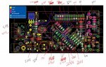
Bryan, sorry it took so long to get a response back to you, trying to work from home with kids who need help on homework is a bit tough. I decided to clean up the Q5 area and put the BS170 back into the board. I then measured as you asked and captured the measurements in the attached picture (sorry probably more than you actually wanted to get). Note, I took measurements with the fan at 100% and LCD on the board and off the board (to the readings on the RPi connector). All 12V measurements match that of the picture so I didn't put any annotations on the jpg. If I read your feedback correctly, the ATMega/VCC is holding the middle pin of Q5 at 2.46V (in my case). The 3.3V pins on the ATMega are definitely lower than they should be (except those at AVC and AAE.Errrrrrrrooooo that doesn't sound right at all. The middle hole is connected to VCC which is 3.3V, check it at the ATmegea. The left hole should be pulled up using that 1K resistor next to the power jack, verify both sides of that have 5V. The right pin is driven by the servo output SVO at the ATmega. If those three check out, then unplug power and check continuity between VCC->Middle Pin, Right pin of 1K resistor -> Left Pin, SVO -> Right Pin.
This is all looking from the soldered side of the HeaterMeter board, not the component side I should say. If you have a hard time measuring the SVO/VCC you can run the HeaterMeter without the LCD/Button board attached, just remove it before powering up.