HeaterMeter Hardware v4.3.3, v4.3.4, v4.3.5, v4.3.6


Oh wowie, actually the extra voltage readings are very helpful. You've got some krazy voltages going on there. The key indicator I am seeing though is 3.3V at AVC but only 2.46V or as low as 2.06V on VCC and RST. I'm actually shocked that the AVR is running at all, since it isn't officially rated to run at 16MHz under like 3.5V. I think it is being backfed through the analog power input side and the trace that feeds from the 3.3V regulator, through Q5, to VCC is busted.

Let's try this. Take a small bit of wire and solder it from the + side of the 100uF/10V capacitor between the 3.3V regulator and the ATmega to the VCC pin on the ATmega. Either that or just straight across from AVC to VCC, whichever you find easier to do. At that point hopefully you'll get 3.3V on VCC, RST. If that checks out, check SVO for ~0.290V at 0% output. If we can get that, we can fix the rest.
The VCC is now at 3.3V, but RST only moved up to 2.78V, SVO = 0.16V. Also, the pin on the same side as SVO next to it (Pin3?) is now 0.78V (slightly higher than 0.56V prior), and LE1 is now only 2.3mV
 
Well that's not exactly the stellar improvement I'd hoped for, but you know what? I just learned something. The RST is actually 2.78V. I just assumed that the 10K pullup was just a pullup, but it actually draws more current than I expected. I have 2.8V on my RST pin so that sounds good. I think you're in business, even though the SVO is a little low.

Now put Q5 back in place. You're going to need to solder new connections to it since the pads are damaged. I think your middle one is OK but the other two sound like the are kaput based on your previous measurements. This is it! If this works, it works. If it doesn't, then I'm not sure where to go from here.
servowires.png
 
Well that's not exactly the stellar improvement I'd hoped for, but you know what? I just learned something. The RST is actually 2.78V. I just assumed that the 10K pullup was just a pullup, but it actually draws more current than I expected. I have 2.8V on my RST pin so that sounds good. I think you're in business, even though the SVO is a little low.

Now put Q5 back in place. You're going to need to solder new connections to it since the pads are damaged. I think your middle one is OK but the other two sound like the are kaput based on your previous measurements. This is it! If this works, it works. If it doesn't, then I'm not sure where to go from here.
View attachment 1781
Shazam! Thanks Bryan I think that’s got it....need to do some adjustments on the damper to get it to fully close, but I think that’s a minor task. Appreciate all the help
 
Heck yeah, we did it! Thanks for sticking with it and being such a great set of eyes on your board. Always makes me happy when we can solve a problem like this.

The open and closed positions you just need to edit the "Servo pulse duration" values in the webui and you're good to go.
 
Hi All, I can’t seem to locate the how to create a adapter plate for a pit boss k24? Any help would be appreciated? FYI, I’d rather diy then purchase from bbq guru;)
 
Hi All, I can’t seem to locate the how to create a adapter plate for a pit boss k24? Any help would be appreciated? FYI, I’d rather diy then purchase from bbq guru;)
It is probably the same as all the other ceramic grills. Just get a piece of sheet metal from the hardware store that's big enough to cover the vertical height of the vent, cut a rectangle out of it, then cut a hole in the center and put a 1" NPT nipple in it and secure it with a nut (the EMT conduit ones from the electrical section work really well). The dampers have a 1" NPT adapter that you just screw the other side in. Total cost is gonna be about 5 bucks.

For specific questions like these you'd probably get more views / response if it were its own thread and then it could also more easily found instead of burying it in this generic thread.
 
I have been searching and I cannot find it - Where are the instructions for doing the SMD assembly? I found the testing page, but not the page that described which componetns go where - should I just look at the board diagrams?

Matt
 
I have been searching and I cannot find it - Where are the instructions for doing the SMD assembly? I found the testing page, but not the page that described which componetns go where - should I just look at the board diagrams?
Yup there are only 8 parts and all of them are clearly labeled on the PCB itself what goes where so no external documentation needed. Put the 10k resistors where it says 10k, put the 1k resistor where it says 1k. Put the capacitors in the 1n, 10n, 0.1u positions. Chip goes in the chip footprint.
 
Yup there are only 8 parts and all of them are clearly labeled on the PCB itself what goes where so no external documentation needed. Put the 10k resistors where it says 10k, put the 1k resistor where it says 1k. Put the capacitors in the 1n, 10n, 0.1u positions. Chip goes in the chip footprint.
Thanks Bryan
 
I just figured out that my servo had gone out on me. I bought the same model to replace the servo. I rewired the assembly and when I try to adjust the servo manually, it way overshoots where it's supposed to be. It turns maybe something like 105 degree instead of 90. Anyone know of a way to adjust that?
 
I just figured out that my servo had gone out on me. I bought the same model to replace the servo. I rewired the assembly and when I try to adjust the servo manually, it way overshoots where it's supposed to be. It turns maybe something like 105 degree instead of 90. Anyone know of a way to adjust that?
In the webui, just adjust the servo endpoints for the open and closed position and it should adjust linearly between those.
1605734788762.png
 
I've worked through importing the EAGLE files for the HeaterMeter base and LCD board into KiCad and spent a day fixing the one million tiny problems with the import. Moving forward all PCB development will be done in KiCad and the latest files are now in GitHub. I've also already received a batch of boards using the design and tested assembling a few to make sure they actually work.
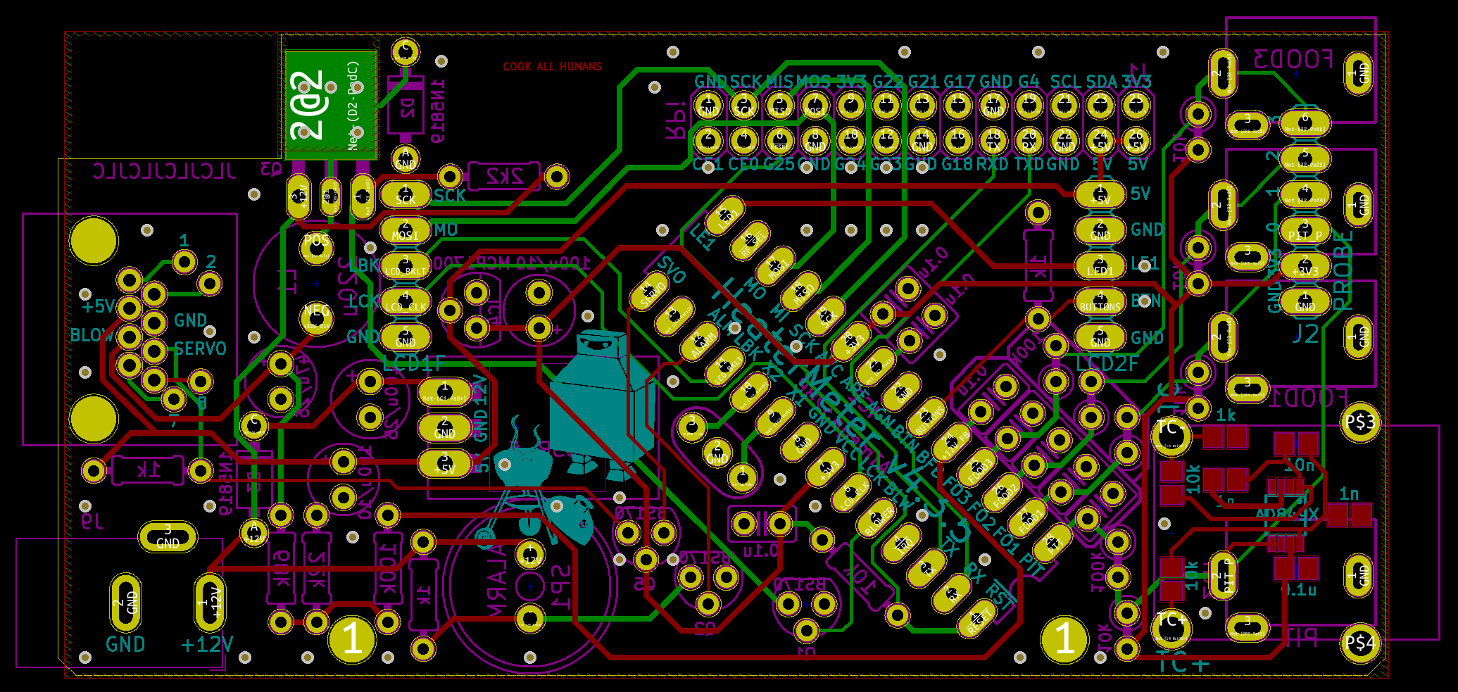
HeaterMeterPI.Board.png


The only thing changed in v4.3.5 is that the probe mono jacks and DC power input barrel jacks now have plated slots since those are now commonly available from board houses for the same low low price (or not low low price if you get them from 4pcb). All the silkscreen has been redone and one trace has been rerouted to pass the updated DRC checks, can you tell which it is!?

I forgot to change the PCC-SMP-K footprint to use plated slots too because of course I did. For anyone who simply must have a 4.3.4 board because you really love putting rectangular pegs in round holes, if you hurry I still have a single one left in the store inventory!
 
After using my HM 4.0 reliably for almost 8 years, I decided it was time to upgrade. A friend asked me to build him one so I took the opportunity to build myself a new one as well and ordered a couple of kits from Bryan over the course of a couple of weeks. I was a mess and ordered the thermocouple when I wanted a thermistor one at first and then shipped back the blower when I supposed to pull it out of the box and keep it. Bryan hung with me and got me setup with the 2 correct kits.

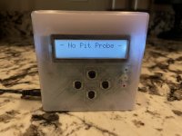
Boy, a lot has changed in 8 years. I love the new 4.3.5 kit and how compact the case is. I built my 4.3.5 kit with a Raspberry 3 B+ and love the built in wifi.

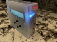
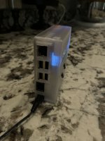
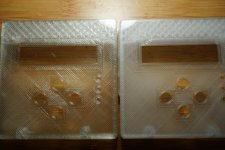
I printed the case in what used to be called clear PETG (now called translucent white I think). I like being able to see the Raspberry status lights through the case.

So glad I upgraded but sad I don't really have a use for my original HM 4 any longer. It has served me well!


IMG_0782.JPG

IMG_0783.JPGIMG_0781.JPG
 
Looks great! I also find it to be a great help to be able to see the Pi LEDs through the case-- is anything happening in there?! I do wish "clear" came out more clear. I've tried all sorts of layer heights and temperatures and still can't get anything but somewhat translucent white. That's why I'm trying to find a better translucent gray since it looks a little less opaque due to lower contrast.
 
Thanks!

Yeah, I have lost track of all the different settings I have tried to get it to print a more clear look but this is about the best I have come up with. This is printed at 100% fill which seems to give it the most transparent look. I still like the look a lot, enough that I have printed every part of my C-Bot printer I am building using this filament.
 
Of course I just complained about how nobody makes a really clear PETG and yesterday I had the first print with a new brand, "Dikale". It's definitely the clearest clear I've ever seen, compared to an old misprint Overture brand one. The overture looks like every other brand I've tried, but this is almost actually clear. Super-cheap too at like $16/kg from Amazon. Exact same settings:

DSC07487.JPG
 
That is super clear compared to the clear PETGs I have tried in the past. I will be ordering a roll to try it out. Nice that it is cheap too. How well does it print up?


Back
Top