Bryan Mayland
TVWBB Hall of Fame
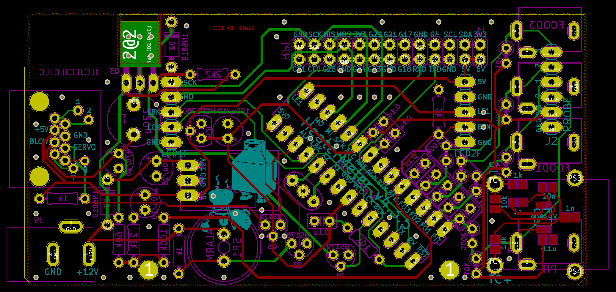
Oh wowie, actually the extra voltage readings are very helpful. You've got some krazy voltages going on there. The key indicator I am seeing though is 3.3V at AVC but only 2.46V or as low as 2.06V on VCC and RST. I'm actually shocked that the AVR is running at all, since it isn't officially rated to run at 16MHz under like 3.5V. I think it is being backfed through the analog power input side and the trace that feeds from the 3.3V regulator, through Q5, to VCC is busted.
Let's try this. Take a small bit of wire and solder it from the + side of the 100uF/10V capacitor between the 3.3V regulator and the ATmega to the VCC pin on the ATmega. Either that or just straight across from AVC to VCC, whichever you find easier to do. At that point hopefully you'll get 3.3V on VCC, RST. If that checks out, check SVO for ~0.290V at 0% output. If we can get that, we can fix the rest.
Let's try this. Take a small bit of wire and solder it from the + side of the 100uF/10V capacitor between the 3.3V regulator and the ATmega to the VCC pin on the ATmega. Either that or just straight across from AVC to VCC, whichever you find easier to do. At that point hopefully you'll get 3.3V on VCC, RST. If that checks out, check SVO for ~0.290V at 0% output. If we can get that, we can fix the rest.

")