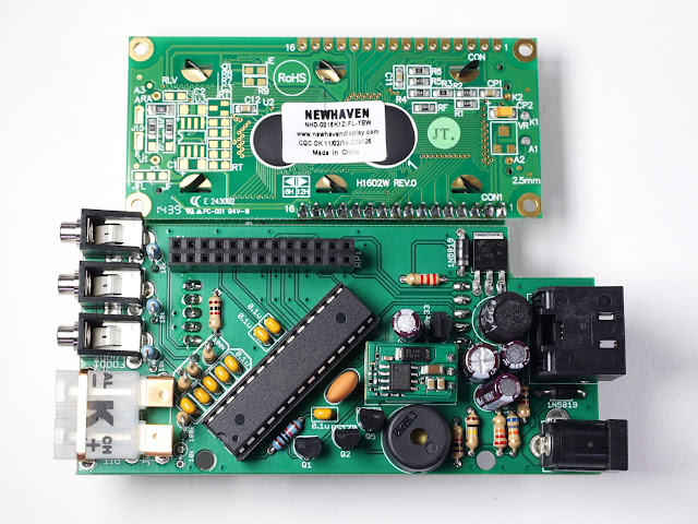
HeaterMeter Hardware v4.3.3, v4.3.4, v4.3.5, v4.3.6


Bryan Mayland

TVWBB Hall of Fame
HeaterMeter Hardware v4.3.6

It must be really cold somewhere because I'm publishing the HeaterMeter v4.3.4 design finally. EDIT: Updated to v4.3.4, v4.3.5, v4.3.6
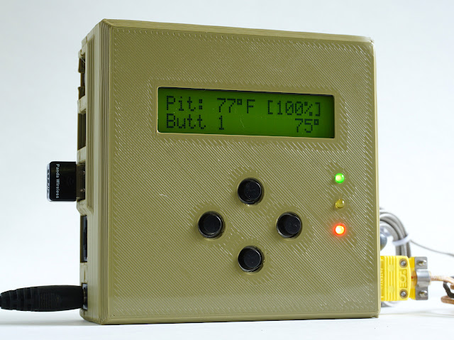
DSC02281.JPG


What's New
Absolutely nothing! This design is just a refresh to replace obsolete components from the 4.2 design: the 4-way switch and the original Raspberry Pi form factor. The new design is thicker but less wide, however the overall volume (with case) has increased from 339cm3 to 371cm3. The design sports 4 individual buttons instead of the single 4-way switch and use common 12x12mm tactile switches which are available from a variety of sources.

Much thanks to Kevin Akers who redid the base board layout from scratch!
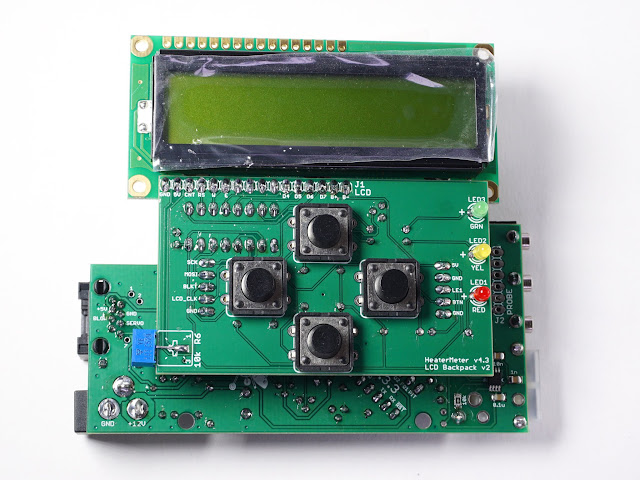
DSC02253.JPG

DSC02255.JPG


Full Comparison
  • HeaterMeter v4.2.4
  • Raspberry Pi Model A or B (original), Raspberry Pi Zero / Zero W, or Raspberry Pi Model A+ (with modification)
  • Wider, thinner form factor
  • Dimensions: 127mm x 92mm x 29mm (339cm3)
  • Single 4-way directional button
  • Slightly cheaper due to single PCB design

  • HeaterMeter v4.3.6
  • Raspberry Pi Model A+, Raspberry Pi Model B+, Raspberry Pi 2 Model B, Raspberry Pi 3 Model B, Raspberry Pi Zero / Zero W
  • Narrower, fatter form factor
  • Dimensions: 102mm x 101mm x 36mm (371cm3)
  • Four (4x) discrete buttons

HeaterMeter 4.3 Hardware
HeaterMeter 4.3 Assembly
HeaterMeter v4.3 Assembly Photo Album
HeaterMeter v4.3 PCB schematics, boards, and renders

All the schematics, EAGLE (v4.3.3 and v4.3.4), and KiCad (v4.3.5, v4.3.6) files are available from the GitHub Project as well as the above link. A 3D printed case source file is also there. Troubleshooting images and assembly videos are coming as I churn them out. I've spend a week and a half just generating all the documentation, projects, BOMs, illustrations, and as always everything HeaterMeter-related is faster and more fun.

The case design is up on Thingiverse where you can customize it to fit different Raspberry Pi and Thermocouple/Thermistor options. Printed cases are also available in the HeaterMeter store. It only took this many tries to get it where I liked it.

DSC02302.JPG


HeaterMeter v4.2 is still active and I'll be continuing to stock v4.2 in the HeaterMeter store at least until the software support for newer Pis is complete.
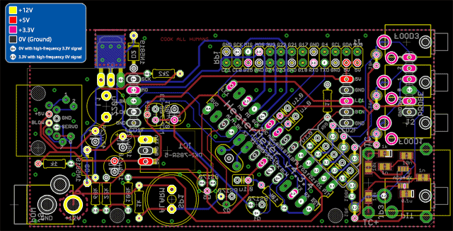
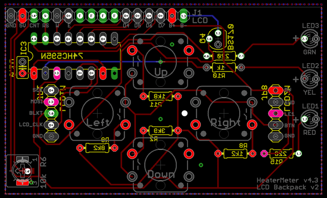
HeaterMeter433LcdV-thumb.png


Here's some voltage debugging. The base board is a thermocouple PCB with a default configuration and with no probes plugged in. For a 4-probe thermistor version, all the probes will read the same 3.3V and 3.2V closer to the microcontroller. Then plug in a probe into the Pit jack and the blower should turn on (the default setpoint is 225F so a room temp probe should activate it I think? Might depend on the probe model). The "1.4*" on the LCD board is the contrast pot adjustment, so that should be in the 1.4V ballpark but the same voltage at the two points.
 
Last edited:
Added a link to the 3D files on Thingiverse where you can customize the case with what options you want. I bet I could make one with no LCD/buttons too but that's further down the road if people ask for it.
 
Any reason why you cant use the 4.3 on an original Raspberry Pi B?

My guess would be that the USB or LAN port on the model B interferes with something on the HMv4.3 board, but I don't know for sure...

I think the main reason for the HMv4.3 is to add newer model rPi support because the rPi model B is getting hard to find. Since there are no real upgrades in HMV4.3, just newer rPi support (for the physical connection), I would think if you already have a rPi Model B you should just build a HMv4.2 board for it. In the end you will have the same thing functionally, the HMv4.2 is a time tested design that has outstanding performance.
 
This is awesome! Can't wait for the v14 software to come through. I built a few 4.2.4 units this summer and those Pi's are really getting harder to find. I managed to get my hands on a couple of pi zero's but their USB cable/port was hard to cram into the case.
 
I've updated the case design a little on Thingiverse. Some minor tweaks to help the two halves come closer together, and a some lips around the inside to align the halves and keep them from sliding laterally. Will be in github on the next push.
 
Hi Bryan, I recently put together a HM 4.3 which I purchased from your store, followed very detailed easy to follow instructions, unfortunately the thermocouple output is not working. I have used it for a couple of cooks with the other probe jacks, which is fine, but I would like to rectify the issue. I ran across some trouble shooting for the T/C on the 4.2 version which was done in an incomplete state. Would you be able to provide similar test points/values for a completely assembled 4.3? Thanks in advance for any assistance you are able to provide.
 
Can you describe in more detail what's not actually working? Are you getting any readings? In the web config, have you changed the probe type from Internal to Thermocouple?
 
What's wrong with the thermocouple input? Is it just always saying "off"? Do you have the probe type set to Thermocouple 5mv/C? Did you remember to NOT insert the 10k resistor by the thermocouple but DO insert the 100k (in their proper holes, not putting the 100k in the 10k hole)?

All the thermocouple boards undergo the testing procedure to make sure they work properly before they are sold so it should certainly work. You can check the continuity using the same reference image from the 4.2 board in the wiki with the device not powered, however the 5-4-2 running down the left side is actually brought out to the probe expansion header above it. 5="3V3" 4="0" 2="GND". With the board powered, the voltages should be right too, except instead if it being 9V because you're testing with a 9V battery, it will be ~3.3V. If you insert a wire into the thermocouple to short the connection, the output voltage should drop to ~100-200mV depending on the temperature. If it does not, verify that you do not have that 10k ohm resistor installed. If the voltage does drop make sure you've got your 100k resistor installed and you should see the same voltage at Pin 28 of the ATmega (the microcontroller pin closest to the thermocouple jack).

If the voltage does not drop and you do not have the 10k resistor in, you might want to try taking a dry soldering iron (no solder, completely clean) and laying the tip flat against the pins on each side of the amplifier for 5 seconds to re-flow them.
 
With probe0 set as thermocouple no reading at all, have tried with different k-type T/C's which work fine with my DVOM with has a mini T/C jack. With probe0 set to internal an ambient temp is displayed.
 
I found what I believe to be the self inflicted problem with the thermocouple circuit, the surface mounted 10k resistor closest to the positive lead on the thermocouple connector was damaged. I am guessing this was done during the soldering of the thermocouple lead. Thanks for your help in leading me to finding the problem.
 
I found what I believe to be the self inflicted problem with the thermocouple circuit, the surface mounted 10k resistor closest to the positive lead on the thermocouple connector was damaged. I am guessing this was done during the soldering of the thermocouple lead. Thanks for your help in leading me to finding the problem.
Doh! If you need to replace the 10k SMD resistor, I can mail you a new one (actually a few because they are easy to lose in singles). It isn't too difficult if you have some tweezers and align the tip if your soldering iron so it touches both halves of the pad at once or just go back and forth quickly with the tip.
 
Just building up the LCD board now for my 4.3.3. It looks like some of the resistor values in the Mouser order links are for the ohms values when they should be kiloohms. This applies to R2, R9 & R11 on https://github.com/CapnBry/HeaterMeter/wiki . I was wondering what the 1R8 resistor was going to be used for :-).

I'm going to try and use a generic LCD module (Truly MCC162) I had lying around as it looks the same shape and I think it has a compatible controller. I've cut the trace that earths the backlight and was planning on adding a 15R resistor as this module doesn't have one built in.
 
Bryan,

Great work on the 4.3. I bought a few boards, and plan on assembling a few this arvo. I love the 2 board design. It introduces a bit more versatility regarding where the interface sits vs. the brains/guts.

The case I'm printing now, and although a great design, I see a flaw in the top part of the case being a bit too thick, and the "pillars" between the rPi components on the side of the case may have a tendency to snap off (don't ask me how I know). I am not against a case that's equal thickness parted, and certainly not against the 4 screw rule. I know you're busy, and if you can't do it, and if you will allow me to, I would be happy to design an alternate case.
 
Just building up the LCD board now for my 4.3.3. It looks like some of the resistor values in the Mouser order links are for the ohms values when they should be kiloohms. This applies to R2, R9 & R11 on https://github.com/CapnBry/HeaterMeter/wiki . I was wondering what the 1R8 resistor was going to be used for :-).

I'm going to try and use a generic LCD module (Truly MCC162) I had lying around as it looks the same shape and I think it has a compatible controller. I've cut the trace that earths the backlight and was planning on adding a 15R resistor as this module doesn't have one built in.

Ah man, I just bought 100 of each of those!

Bryan can you change the buttons to the components you have linked too. lol.
 
Just building up the LCD board now for my 4.3.3. It looks like some of the resistor values in the Mouser order links are for the ohms values when they should be kiloohms. This applies to R2, R9 & R11 on https://github.com/CapnBry/HeaterMeter/wiki . I was wondering what the 1R8 resistor was going to be used for :-).
Whoa good catch! Sorry you've probably ordered the incorrect resistor values but you're right the links are wrong. I've updated the wiki with the correct part links. This affected 1k2, 1k8, 3k9, and 8k2 resistors used in the LCD board.

@John Bostwick: Those are 12mm tactile buttons with 8.5mm round actuators. The HeaterMeter kits come with 7.5mm tapered round actuators but I can't find a source for those from Mouser and mine come in a giant bag from China. I spent several hours combing the search results, reading datasheets, and buying samples. None of them are what I want. The linked buttons also are off-purple color and have a hole through the center of the plunger. All the buttons I ordered were like this so I said "f--- it, I give up". eBay has them in virtually any length.

@WBegg: What do you mean the top part of the case is too thick? Do you mean the split point on the Pi connector side isn't at the right height for your liking? It's gotta split those connectors somewhere. The largest pillar is 14.8mm tall, starts 5mm from the base, and the split is at the 9mm part. That means you get 4mm on one side and 10.8mm on the other side. Sure, that's not symmetrical but try to snap off the pillar by the ethernet jack. Was it just as easy? Well that pillar is 8mm tall, which is really darn close to what both sides of the USB pillar would be if it were split there. I don't think it matters if it is 10.8mm or 7.5mm tall, it is always going to be easy to break off. I would say be sure your slicer is generating solid pillars of plastic for these, because if they're not, they will be very fragile.

There's really not any way to make them stronger because they have to fit the Pi connectors and the USB ports have extended edges which makes the space between them so small that I can't even really fit a rib in there that does any good. You can always just increase the wall thickness if you want to make them sturdier, but that's not going to make much difference either, especially if they're not filled by your slicer.

There's also no room for 4 screws, thus the hinged two screw design. You might be able to squeeze in 3 screws, but the Pi is where the fourth screw would need to go. You'd have to make the whole case roughly 10mm taller to fit the posts. I also tried to get away from having screws that went all the way through and had nut traps on the back because those are always a little hit or miss unless printed really well.
 
I think you read my response wrong, lol. I ment that I order the 100 of each of the wrong resistors you had linked toof. So, I was wondering if you could change the software to activate on the different resistors that were mistakenly linked too.


Back
Top