You are using an out of date browser. It may not display this or other websites correctly.
You should upgrade or use an alternative browser.
You should upgrade or use an alternative browser.
General 3D Printing Thread
- Thread starter Bryan Mayland
- Start date
Since I am a newbie I thought I would throw something out there I just learned yesterday. I know everyone has there favorite CAD software and for me it is limited to what is inexpensive. I found out yesterday that if you are a US military veteran, Solidworks will give you a free copy of Solidworks 2013 professional. You just pay $20 shipping and handling. I filled out the application and sent them a copy of my dd214 (discharge papers) and paid the $20. Just got a shipping confirmation this morning. If nothing else, it will be something else to learn.
Here is the link:
https://store.solidworks.com/veteran/default.php
Here is the link:
https://store.solidworks.com/veteran/default.php
I'm using the e3d hotend. I've had it in full operation for about 3 months I think. I have been very happy with it, no gotchas so far.
Thanks for the info. Can you post your slic3r settings so I can compare once I get my new hotend in please?
This is what I use for high quality prints. I don't set my temps in slic3r configs, I do it manually so that I can have the same gcode for different filament types. Generally I print ABS at 230 and PLA at 200. My bed temps on PEI are 100 for ABS and 60 for PLA measured at the aluminum heat spreader surface.
avoid_crossing_perimeters =
bed_size = 300,250
bed_temperature = 0
bottom_solid_layers = 3
bridge_acceleration = 1000
bridge_fan_speed = 100
bridge_flow_ratio = 1
bridge_speed = 40
brim_width = 0
complete_objects = 0
cooling =
default_acceleration = 1000
disable_fan_first_layers = 1
duplicate = 1
duplicate_distance = 6
duplicate_grid = 1,1
end_gcode = G1 X0\nG1 Y240\nM104 S0 ; make sure the extuder is turned off.\nM140 S0 ; make sure the bed is turned off.\nM84 ; shut down motors
external_perimeter_speed = 75%
external_perimeters_first =
extra_perimeters = 1
extruder_clearance_height = 20
extruder_clearance_radius = 20
extruder_offset = 0x0
extrusion_axis = E
extrusion_multiplier = 1
extrusion_width = 0.5
fan_always_on =
fan_below_layer_time = 60
filament_diameter = 3
fill_angle = 45
fill_density = 0.25
fill_pattern = honeycomb
first_layer_acceleration = 0
first_layer_bed_temperature = 0
first_layer_extrusion_width = 0.5
first_layer_height = 150%
first_layer_speed = 60%
first_layer_temperature = 0
g0 = 0
gap_fill_speed = 20
gcode_arcs = 0
gcode_comments = 0
gcode_flavor = reprap
infill_acceleration = 1000
infill_every_layers = 2
infill_extruder = 1
infill_extrusion_width = 0.5
infill_first = 0
infill_only_where_needed = 0
infill_speed = 100
layer_gcode =
layer_height = 0.195
max_fan_speed = 100
min_fan_speed = 35
min_print_speed = 20
min_skirt_length = 0
notes =
nozzle_diameter = 0.4
only_retract_when_crossing_perimeters =
ooze_prevention = 0
output_filename_format = [input_filename_base].gcode
overhangs = 1
perimeter_acceleration = 750
perimeter_extruder = 1
perimeter_extrusion_width = 0.5
perimeter_speed = 40
perimeters = 3
post_process =
print_center = 150,125
raft_layers = 0
randomize_start =
resolution = 0
retract_before_travel = 2
retract_layer_change = 1
retract_length = 1
retract_length_toolchange = 0
retract_lift = 0.24
retract_restart_extra = 0
retract_restart_extra_toolchange = 0
retract_speed = 40
rotate = 0
scale = 1
skirt_distance = 6
skirt_height = 1
skirts = 3
slowdown_below_layer_time = 15
small_perimeter_speed = 20
solid_fill_pattern = rectilinear
solid_infill_below_area = 70
solid_infill_every_layers = 0
solid_infill_extrusion_width = 0.5
solid_infill_speed = 75%
spiral_vase = 0
standby_temperature_delta = -5
start_gcode = G28 ; home all axes\nG29; auto bed level
start_perimeters_at_concave_points = 0
start_perimeters_at_non_overhang = 0
support_material =
support_material_angle = 0
support_material_enforce_layers = 0
support_material_extruder = 1
support_material_extrusion_width = 0.5
support_material_interface_extruder = 1
support_material_interface_layers = 0
support_material_interface_spacing = 0
support_material_pattern = rectilinear
support_material_spacing = 4
support_material_speed = 60
support_material_threshold = 0
temperature = 0
thin_walls = 1
threads = 2
toolchange_gcode =
top_infill_extrusion_width = 0.5
top_solid_infill_speed = 75%
top_solid_layers = 3
travel_speed = 130
use_firmware_retraction = 0
use_relative_e_distances = 0
vibration_limit = 0
wipe = 0
z_offset = 0
RalphTrimble
TVWBB Diamond Member
Is anyone here using a Hall Sensor for and endstop? I am FINALLY getting around to replacing the mechanical end stop on my printer. I was gonna go optical, but now I am leaning toward a hall sensor cause I think a magnet on the end of a screw would make an adjuster easier than I could make for optical.
I am finding lots of optical endstops, but not really any hall sensor endstops (pre-made), so I am asking if anyone knows of a hall sensor that works well as an endstop?
I am finding lots of optical endstops, but not really any hall sensor endstops (pre-made), so I am asking if anyone knows of a hall sensor that works well as an endstop?
I got a Hall-O sensor for my z axis. It has a small pot for adjustment. It is very nice. http://reprap.org/wiki/Hall-Θ
RalphTrimble
TVWBB Diamond Member
I got a Hall-O sensor for my z axis. It has a small pot for adjustment. It is very nice. http://reprap.org/wiki/Hall-Θ
Sweet, thanks for that feedback. Since I posted I had run across a couple similar looking units. I think a hall sensor is the way to go, so I'm gonna try one out..
Neil Mager
TVWBB Member
I'm using them for all 3 axis. I have 2 from reprap discount and one from ultimachine. All seem to work very well. I drilled a small hole in either the plastic or the bed to hold the magnets and press
fit them in (or a little white glue if necessary).
Good luck!
fit them in (or a little white glue if necessary).
Good luck!
RalphTrimble
TVWBB Diamond Member
Thanks Neil, Ultimachine is the first source I've found in the US (other than some I found on Amazon recently). I may give Ultimachine a try, how has your experience been with them?
Neil Mager
TVWBB Member
They are very easy to work with, fast shipping and support. I also get my plastic from them. The filament from them is excellent. I've tried other less expensive vendors and had extruder problems, switched back to ultimachines plastic
(with no changes to settings) and I can get very long prints with out any jams. And no, I have no connection to them, other then a being a satisfied customer!
(with no changes to settings) and I can get very long prints with out any jams. And no, I have no connection to them, other then a being a satisfied customer!
Thanks Neil, Ultimachine is the first source I've found in the US (other than some I found on Amazon recently). I may give Ultimachine a try, how has your experience been with them?
They are very easy to work with, fast shipping and support. I also get my plastic from them. The filament from them is excellent. I've tried other less expensive vendors and had extruder problems, switched back to ultimachines plastic
(with no changes to settings) and I can get very long prints with out any jams. And no, I have no connection to them, other then a being a satisfied customer!
Agreed. Very good company, I used them for a while for filament until I found other suppliers.
RalphTrimble
TVWBB Diamond Member
I FINALLY got around to replacing the mechanical endstop switch on my Z axis to a hall sensor last night. It went really easy, wires straight up to the endstop header like the mechanical switch except you need to add the third wire for +5v. It worked really easy, though I did have to set the Marlin firmware to invert the Z endstop. I ended up ordering these units from Amazon, got 3 for $14 bucks with free two day delivery. (went with Amazon cause it looked like a good deal and I trust their fast two day delivery with the Prime service). Amazon came through as expected, the unit worked as expected, so I am happy. It seems to be very accurate but time will tell. It was only over time that the mechanical endstop became a PITA when suddenly the z axis is out of whack for no reason. The z-axis adjuster screw on the MakerFarm i3 leaves something to be desired, I think it wiggles around a bit and, or perhaps it's just the switch. At any rate, so far the hall sensor seems to be the cats a$$! I went with magnetic over optical because I read lighting conditions can effect the opto's, I worry a bit about printing debris getting in the opto, and the adjuster was easier to make for the magnetic sensor. (magnet on the end of a screw)
Right now I am using the analog output from the hall sensor, the only thing I don't like is the switch doesn't let go until the magnet moves away from the sensor a bit. This means you need to raise the head a bit before you can tell it to home again. I am still looking into the digital side of the sensor, I'm pretty sure I can use it but not sure if there is an advantage? If I could home the z-axis without raising the head while using the digital output that would be nice, but not sure if that is the case or not...
Right now I am using the analog output from the hall sensor, the only thing I don't like is the switch doesn't let go until the magnet moves away from the sensor a bit. This means you need to raise the head a bit before you can tell it to home again. I am still looking into the digital side of the sensor, I'm pretty sure I can use it but not sure if there is an advantage? If I could home the z-axis without raising the head while using the digital output that would be nice, but not sure if that is the case or not...
Bryan Mayland
TVWBB Hall of Fame
The reason your hall sensor has to back up before it resets is because it is analog. As it gets closer the voltage gets higher until it passes the "HIGH" threshold for the ATmega, which is like 0.8 * VCC. Then in order for it to go low it needs to go below something like 0.2 * VCC, so the endstop has to move past the deadband.
I believe the digital output is a single threshold, looking at the schematic, so it is "On" above a certain point and "Off" below that. With no deadband except a very tiny negligible switch threshold.
I believe the digital output is a single threshold, looking at the schematic, so it is "On" above a certain point and "Off" below that. With no deadband except a very tiny negligible switch threshold.
RalphTrimble
TVWBB Diamond Member
Bryan, I was hoping the digital output would be better in that regard, sounds like it is. I will have to experiment with that sometime soon, cause the unit does have digital output as well as analog. (although this unit doesnt have the fine adjustment pot like some others do)
As for mounting, I decided to put it on the left z idler instead of the right because there is so much going on at the right it is a PITA to access over there. I got sick of reaching between the filament, my light, and behind the idler to make adjustments. I put it right up front where I can access it easily. I just printed a quick mount for the sensor that clamps onto the smooth rod, then made a quick mount for the screw that goes on the idler, then made a coupler that puts the magnet on the end of the screw. I used a magnet I had laying around from a custom guitar pickup project I worked on some time ago. The first draft of the parts wasn't perfect but works...
Here is a picture....
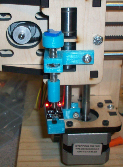
PS the part that mounts the screw on the idler grips the wooden frame on the end, that is why it only needs one screw....
EDIT:
I switched over to using the digital pin on the hall sensor and it's even better. The z-axis now homes just like it did with the mechanical endstop but much more accurate. Either way the hall sensor works and is very accurate, but it would have been a PITA to have to lift the head 3mm any time you wanted to home it. Also, in digital mode you don't have to invert the z endstop in the firmware.
BTW, I am using an audio cable from an internal CDROM to connect the hall sensor board to the RAMPS board, you just need to re-arrange the wires to match the pinout depending if you want the digital or analog pin. The RAMPS pinout is always Signal-GND-VCC (mechanical endstops use SINGAL-GND only)
As for mounting, I decided to put it on the left z idler instead of the right because there is so much going on at the right it is a PITA to access over there. I got sick of reaching between the filament, my light, and behind the idler to make adjustments. I put it right up front where I can access it easily. I just printed a quick mount for the sensor that clamps onto the smooth rod, then made a quick mount for the screw that goes on the idler, then made a coupler that puts the magnet on the end of the screw. I used a magnet I had laying around from a custom guitar pickup project I worked on some time ago. The first draft of the parts wasn't perfect but works...
Here is a picture....
PS the part that mounts the screw on the idler grips the wooden frame on the end, that is why it only needs one screw....
EDIT:
I switched over to using the digital pin on the hall sensor and it's even better. The z-axis now homes just like it did with the mechanical endstop but much more accurate. Either way the hall sensor works and is very accurate, but it would have been a PITA to have to lift the head 3mm any time you wanted to home it. Also, in digital mode you don't have to invert the z endstop in the firmware.
BTW, I am using an audio cable from an internal CDROM to connect the hall sensor board to the RAMPS board, you just need to re-arrange the wires to match the pinout depending if you want the digital or analog pin. The RAMPS pinout is always Signal-GND-VCC (mechanical endstops use SINGAL-GND only)
Last edited:
Ralph, why the hall effect sensor instead of an optical one? Just curious.
I took the plunge and bought a mendal max 1.5 printer kit and have been working on getting it up and running. Printed my first test structure last night, and got 10-12 layers before it delaminated from the mirror. I should get my Ultem sheet from McMaster today, so hopefully that will fix that issue. The test structure was a simple 1"x1"x.5mm square. It actually turned out quite nice. Still need to do further testing, printing the entire part, a couple more test structures, then I'm ready to give something else a try.
I'll probably print a case to hold the ramp board first, then I need new x-axis ends to fix an issue with the kit I got.
Thanks to Tom for his continued support and getting me here.
dave
I switched to a hall sensor so I could remove all the mechinical adjustment of my z axis. It allows you to adjust 1-6 mm z travel via a pot. My experience with mechanical z adjusters would change slightly after lots of printing probably because of vibration from printing fast.
That kind of accuracy is less important for x and y axis and optical is what i would use if I wasn't so cheap. :>
I think I will be upgrading my print surface next. I'm still waiting to hear a few more experiences before i take the plunge.
That kind of accuracy is less important for x and y axis and optical is what i would use if I wasn't so cheap. :>
I think I will be upgrading my print surface next. I'm still waiting to hear a few more experiences before i take the plunge.
RalphTrimble
TVWBB Diamond Member
Ralph, why the hall effect sensor instead of an optical one? Just curious.
dave
Well, couple things. First off, with an opto you need something to break the light. That something is usually flat so it can slip into the opto's thin slot. That something also has to go up and down to make the adjustment. It was harder for me to conceive of an easy way to move this flat item up and down without having it rotate (cause it needs to land in the slot after adjustment). Secondly, I've read that lighting conditions can effect the opto, and I usually have a goose neck light pointing at my print so light may be coming from different angles.
With the hall sensor for the adjuster I just need a magnet on the end of a screw, easy peasy (cause the magnet can rotate). And the hall sensor will not be effected by lighting conditions. I've also read the hall sensor can be more accurate (though I am sure an opto with consistent light would be quite accurate as well). Since the hall sensors cost me less than $5 each cost wasnt a concern, so I went with what seemed like would be the easiest to implement and the most accurate.