General 3D Printing Thread


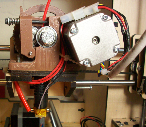
I put an optical sensor on my i3 and printed a little strip that would come down and interrupt the beam.


I printed the strip so it would endstop before the head got to the bed, but at the same place every time. Then I just would enter the offset as printer initialization G-code. If the head was 3.1415mm from the bed, you home, then G92 Z3.1415.

It is another one of those things where it isn't on/off, but rather the voltage changes based on how much light is getting to the receiver. As the strip went in between you could see the voltage change as the edge diffused the light and "slowly" winked it out. I believe it was affected by ambient light as well. I would say it was repeatable to within 0.02mm assuming nothing changed, and at most 0.15mm from one use to another.

I switched to the servo system which works alright. The autoleveling I don't use, but using a servo as the z endstop works well enough. The Hall endstop is probably better, cheaper, and easier.
 
I printed the strip so it would endstop before the head got to the bed, but at the same place every time. Then I just would enter the offset as printer initialization G-code. If the head was 3.1415mm from the bed, you home, then G92 Z3.1415.

Yah, I thought of that too, use a software offset to set the z-axis position with the opto and interrupter mounted in fixed positions. I decided that I prefer the actual physical adjuster screw over a software offset, and since hall sensors are really cheap, accurate and reliable it was an easy decision to make. The only hesitation with the hall sensor was because the physical and opto endstops seem to have more documentation online, and there is such a wide variety of hall sensors available. I don't think a RAMPS setup will be too picky about the sensor, though I would recommend that you make sure you get one that includes a digital output, the analog output will work but it's more of a PITA, the digital output works awesome.

I had my mechanical endstop switch mounted solid with screws (not with wire ties) so I know it wasn't moving, still z-axis homing was dicey at best. The screw adjuster on the MakerFarm wooden frame leaves lots to be desired, TBHWY I don't know how they expected it to work at all, unless I missed something in the assembly. The screw fit loose enough in the hole that it could wiggle and move or even get pushed back by the switch. I put some thick solder braid into the screw hole and then threaded the screw over that, the screw was stable at that point and adjusted up and down the way I wanted it, still the z-axis homing was dicey. The switch itself leaves a bit to be desired in this application where such a high degree of accuracy is required, for the X and Y axis the switch is fine and I don't plan on changing them...
 
Nah. No kit. I doubt I'd ever offer it. However, it's freely available on my github. There are a lot of new parts that I need to publish as well. I really need to get on that.
 
I've been toying with the idea of putting together a second more custom made printer. I would love to get a look at your design before I dig in too far... What is the URL to find it?
 
https://github.com/akhlut/PrismMendel_1.5

Like I said, this is a year old at this point. There are so many changes to the machine at this point - nothing major, but part tweaks and multiple versions of a single part for different situations/components. That and the whole thing is drawn in 123D. I really should just re-draw it in Inventor Fusion to incorporate all the changes and upgrades.

This weekend I am committed to another project, but if I get some time I'll update github with the changes to Prism Mendel 1.5
 
Hey Matt, what is the advantage of Xstepper over something like RAMPS besides the fact that it runs grbl? When I was researching controllers for my CNC, I couldn't really come up with an advantage for grbl vs. marlin so I'm interested to hear what you've found. I'm currently using my old RAMPS 1.4 with the panucatt steppers at 24V and have been milling wood, aluminum, and SS with good results. I've found that the most important part of the whole process is the CAM aspect and have focused most of my attention there.
 
Cost. Xstepper can be built for less than $50, less than $40 if you eliminate some of the unnecessary components. In the end it may be the cheapest solution for driving a hobby mill.

I think the biggest difference is that grbl supports arcs, whereas marlin doesn't. Marlin is just too much, especially for some people who aren't comfortable with re-flashing firmware, let alone changing pin assignments. Don't get me wrong, Marlin is fantastic firmware, and you can modify it to do whatever you want. But there is so much going on in Marlin that just isn't directly applicable to a mill. Kind of like driving an F-1 car to work every day.

Thermistors would be nice to monitor spindle temp, but not really necessary. And the 5th driver would be nice for a dedicated A-axis, but not too many people have a need for one. I think the main advantage of Marlin is the ability to natively use LCD's and SD cards. GRBL can't support them as it's bumping up against the memory limit of the 328p. :(

What xpix and I have done is to try to produce a low-cost, hand-solderable, full-featured GRBL controller. 097u4 is just the latest iteration of the controller. A 1.0 controller will be out by summer at the latest.

Some features:

A-axis or dual-Y-axis support. Two simple solder jumpers provide for easy configuration.

Air tunnel beneath stepper drivers. Pololu IC's should be cooled from the bottom of the chip. 097u4 provides an unimpeded path for air and heatsinks beneath the chips.

Selectable motor headers. You can use either 2.54mm male headers or 5mm screw terminals.

Dedicated power port for stepper drivers. Drive steppers at whatever voltage you decide. Solder in voltage-appropriate 100uF caps and you're good to go.

Galvanically isolated USB. I designed a USB stick for XStepper that provides isolation from the host PC. This helps eliminate ground loops and provides a stabler communications link. Same pinout as the Sparkfun FTDI basic.

Bluetooth support.

On-board FTDI. This is either going to become the standard or disappear. We haven't decided yet.

Pendant support - Feed/Hold and Cycle/Start buttons supported to pause and resume jobs. Auto/manual control of (4) outputs for things like spindles, vacuums, air compressors, etc.

Opto-isolated outputs - Breakout board to drive external components. Galvanic isolation for all output ports to protect the XStepper main board.

Other modules in the works:

XLCD - xpix has a functional prototype of an LCD for GRBL. He's working on extending it to enable headless operation (SD card, etc).

XPID - spindle controller. This is still in the prototype stage. I've had a schematic drawn up for some time, but have neglected to create a board for it. That and the firmware will need to be written. There are some open source spindle controllers out on the internet, and we'll be borrowing various things from them.

So there is a lot that has been done, and a lot that needs to be done.

I would completely agree with you - CAM is a new animal all together. It took me longer than I like to admit on how to figure out the basics of CamBam - RTFM!
 
Very impressive. I figured that if I was ever going to change anything I would wait till Mach4 to see what improvements they could come up with but this sounds very intriguing.
 
I got my Ultem sheet from McMaster today and did my first print. 22x22x10x.5mm thick

2014-01-17_18-24-22_143_zpscc15823a.jpg


At first I thought something was off because my calipers measured it about 10% larger that expected. I then use my calipers to check my 10mm hex wrench and now I get to buy new calipers! I wanted some metric ones anyway. What calipers do ya'll use?
 
Did some maintenace/upgrades on my printer this weekend and she is printing better than ever! Here's a little blog about it...

First I added the hall sensor for the z-axis endstop (which I detailed already)

Next I added a relay to the heated bed circuit that connects the bed directly to 12V rather than being driven by the RAMPS board (the RAMPS board output flips the relay). I clocked the rise from 30C-110C at 10 min before I added the relay, about 7-8 min after. No major improvement really but every little bit helps when it comes to warming the bed. There's a rather pronounced audible click when the bed turns on/off now, not sure if I like that or not. I guess it could get annoying, but it also will remind me if I have the bed heating while I am sitting here typing at the computer....

I pulled the J-Head hotend apart and did some maintenance, 'cause it started printing funky after I ran a bit of black filament through the machine (turns out the black filament was on the fat side of 3mm more than the filaments I had been using) The PTFE liner in the hotend was pretty toasted... The bottom end that goes into the hotend was discolored and shrunken down to the point it was difficult to push the filament through (the black more than the rest). I was able to widen the PTFE a bit and do a little printing with it in the meantime, but it needed to be replaced. (If you have a J-head hotend I recommend that you keep a spare PTFE liner on hand cause this is considered a "consumable" part that WILL eventually exhibit the issues I posted about above and need to be replaced. You will most likely discover the problem precicely when you NEED to get a print done :))

While apart I cleaned the nozzle with a blowtorch, I have to say this is the way to go for cleaning the nozzle. I've cleaned it before using acetone and heat, manual tools etc but the blow torch was easier and worked better. Just put the nozzle on a wire rod or something (through the heater hole) and torch away, flip it upside down to let the remaining filament drip out, burn it out good and run under water.... done! I wiped it down with some alcohol and cleaned the ash out of the inside of the nozzle with an alcohol soaked Q-tip and it was clean as a whistle!

This time around I installed a 40W ceramic heating cartridge in the hotend instead of the resistor. The resister had actually been working fine for me, the hotend always hit temp fast and held it, but I broke one leg off the resistor trying to remove it and decided to try a cartridge instead. The cartridge fit in the hole nicely but sticks out a bit on each side. no biggie.. It works great as well.

When wiring up the hotend I installed a molex connector for the heater and thermister. I am building up a .35mm hotend now and I wanted to be able to swap from .5 to .35 without doing any wiring, so I decided to add a connecter at the hotend, that worked out great as well.

Here is a pic of the hotend with the ceramic heating cartridge and molex connecter in place:
HotEnd.jpg


I also went back to printing on the double thick glass instead of the thinner stuff. I had moved to the thinner glass cause I figured it would heat faster and add less mass to the print bed. After I got the hall sensor installed my z-axis became much more accurate and I noticed a LOT of variance in height accross the glass that was NOT due to bed leveling, so I decided to move back to the double thick glass because it seems to lay more flat.

In the process I FINALLY mastered the art of Kapton tape! I must say, it's a REAL PITA laying down Kapton tape until you master it, always shooting for a perfect surface end to end and never achieving it... I thought the 7" wide roll would make it easier but the large roll has different difficulties that come with it. My new method works great though... I roll out about an inch, then place a wooden shish-kabob stick on the tape and wrap it. Then I roll out the length of tape needed, cut it, then bathe it in a bowl of water with a tiny bit of dish soap in it, holding it by the wooden stick kinda like a flag. Then I drape the tape down onto the glass from one end to the other letting it fall down naturally on its own, the tape will kinda float on the water. Now take an ID card and squeegee out the water and smooth out any bumps. Work from the middle outwards in a circular pattern until it is PERFECTLY smooth and flat.. (AT LAST!) Now bake the thing on your heated bed and repeat the ID squeegee process to remove remaining water bubbles that appear. This method worked out great for me and is relatively easy once you've got it down...

After all that my printer is tuned up better than ever and printing great looking objects. I will be moving on to working with the new .35mm hotend soon....
 
That ptfe issue has happened to me several times which is why I ended up getting an e3d hot end. It works great so far, the only thing I've found is a little more lifting on the edges that I think is due to the draft created by the fan on the hot end. I'll probably just start printing with brim to resolve that issue, or possibly switching the bed with one of the newly found materials posted about earlier. I've been using glass with hair spray without issue with the j head.
 
That ptfe issue has happened to me several times which is why I ended up getting an e3d hot end. It works great so far, the only thing I've found is a little more lifting on the edges that I think is due to the draft created by the fan on the hot end. I'll probably just start printing with brim to resolve that issue, or possibly switching the bed with one of the newly found materials posted about earlier. I've been using glass with hair spray without issue with the j head.

I had been using just hairspray on glass with nice results, but I was getting too much edge curl for the roto damper parts. Then I started printing on Kapton tape and the prints came out incredibly flat and smooth, much better than with glass/hairspray, so I've been going that route lately. I had thought about checking out an E3 hotend but searching the net I found all sorts of threads about problems printing ABS so I decided to hold off for a while and check out a .35mm J-head nozzle...
 
There are no problems with printing ABS and the E3D hotend, I can assure you. There are, however, many problems with users that don't know what they are doing. The internet is great for finding those people.
 
I got my .35mm J-head nozzle installed last night and I am impressed, the first print was the best print I've ever made! Compared to the .5mm nozzle the extrusion and detail seem very fine. Every aspect of the print seems to be improved now, the first layer is going down better, there is much less occurrence of extra plastic debris during the print so everything just runs smoother. Slicing at .4 is out the window now, but sliced at .3 only takes about 20% more time to print but the detail way better using .3mm layers and .35mm nozzle. I haven't tried slicing finer yet, but I am sure I will be able to print some super fine detail with this setup.

I'm super happy with the .35mm nozzle, if anybody out there is running a J-head with a .5mm nozzle I recomend giving a .35mm nozzle a try. You can use the same body (black part) and PTFE liner, I did buy a new resistor and thermistor for the .35mm nozzle so I can wrap it up and leave it as a unit. (should cost roughly $30 for the parts) With the Molex connector I can just unplug the electronics, twist off the nozzle, twist on the other nozzle and it's good to go. Of coarse having a completely seperate J-Head would be slightly more convenient yet....
 
Last edited:
You were printing at 0.4 mm with a 0.5mm nozzle and 0.3 with a 0.35 mm nozzle? These are way too high for those nozzle diameters. You can easily run a 0.5 mm nozzle at 0.2 mm layer height.
 
The smaller you go with the layer the better the detail, but also the more time it takes to print. With the .5mm nozzle I can get good results with some objects sliced at .4mm, sometimes I have to go down to .3mm. With the .35mm nozzle my first couple prints have been sliced at .3mm and they are turning out awesome...
 
Optimal Layer height is determined by your motor/lead screw combination. You can use this calculator to find the optimal results for you hardware. http://calculator.josefprusa.cz/

I have 3/8-12 acme lead screws (2.1082 pitch) with 1.8 degree motors (1/16 microsteping) which yields zero error at .2003 layer height. I have .35 and .5 nozzles but use .5 most of the time because it yields a wider wall thickness (i.e. prints faster) at the same layer height.

Having a sub optimal layer height is not a big deal with small prints but can create a good amount of error with taller prints.
 
I've just been choosing a layer height that is both smaller than the nozzle diameter and achievable with an even number of steps on the z-axis. It's worked out good for me so far, I've been printing some pretty nice objects. I've been pushing the layer height as high as possible while maintaining quality to make the print as fast as possible. So far I really like printing with the .35mm nozzle cause the detail is better. I've been able to boost the print speed up 40% which makes up the time lost to printing more layers, so I am getting better objects in the same or less time with the .35mm nozzle... what's not to like about that!


Back
Top