The Development Log


I couldn't easily cut through the pinheader plastic once installed but John was on the right track. It is much easier to remove if there are fewer pins together. I did it with 6 pins and it wasn't too difficult to remove, then tried it with 3 pins at a time it was pretty easy to pry the plastic off with a small screwdriver. Added a new LCD to the color gallery, meet "Amber".
IMG_2098.JPG


I have just a few things left to test and measure and then do a "burn test" this weekend on HeaterMeter v4.2. There will be at least one more revision, so about 3 weeks at a minimum. The LCD needed to be moved up 0.635mm to make it fit a little better, the servo boost needs a fix, some other components are slightly nudged. I've also added a detectable "HeaterMeter PCB Revision" so the Pi can tell what it is connected to and what features the board supports. I mean I think I can do that, we'll see when I get the next PCBs made. I did some noise tests last night in the lab and ET-732 and TX-1001 probes seem to be rock solid with the new hardware filtering. I even jammed a screwdriver into the 110V socket ground then made a ground loop between the probe and the screwdriver with my body and there wasn't any noise. I look forward to giving it the barefoot outdoor test, which I am almost certain it will fail.

Speaking of almost certain, I will almost certainly remove the "probe noise lockout" feature in the snapshot that prevents probes from reporting if their noise levels are so high they really should be thrown out. I'm experimenting with just reporting the noise levels in the data stream and indicating it in the webui. The only thing holding this back is the noise lockout has a nice side effect of preventing crazy readings on the first sample when you plug in or remove a probe. I'll have to work out how to properly discard those without adding to much computation.
 
I tried to print a basic case for my v4.2 board last night but the printer did not want to cooperate. For some reason one spot on my ultem bed just refuses to be printed on. I need to move the model so it isn't on that spot or something because it messed up 4 prints last night. I was hoping to see how the screw posts interact with the HeaterMeter PCB or if they need to be adjusted.

Code-wise I implemented bandgap calibration to provide more accurate thermocouple readings in dynamic range mode. It wasn't such a big deal because the uncalibrated version was within 0.3% anyway, but I like this because it is technically more accurate.
 
I've been hard at work trying to get the Ralink wifi adapters working at the same time as the rtl8192cu adapters under OpenWrt. I'm not sure why the kernel-tree 8192cu usb driver doesn't work at all for these devices. It would save so much time. I did confirm that my test ralink adapter worked in both client and AP mode. I want to get simultaneous client and AP mode working too (virtual interfaces) because the 8192cu can't do that and I think it would a nice addition.

For some reason, exporting a gpio on the Pi causes it to reboot now. I'm not sure how long that's been broken but after spending a couple of hours on it I am going to save that issue for the next release. Programming the HeaterMeter firmware through gpio still works fine so it isn't a showstopper.

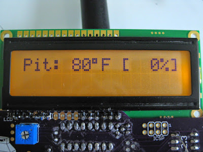
The burn test of the v4.2.3 board over a 12 hour cook seemed to have no problems and "barefoot probe noise" registered around 5mV P-P with my worst adapter. I'm planning on changing the default PID constants to B=0 P=4 I=0.02 D=5. Mainly because I think Ki is way too low currently and the system takes way to long to adapt.

Other default config changes in store
-- Voltage blower output mode the default
-- Reduced servo range by half. These cheap servos can easily get jammed by trying to turn them too far, so the default should be a small range that you then "open up" to find your min/max.
-- Minor tweaks to the probe coefficients to try to reduce the rounding error that comes from webui round trips
-- Change the default LED triggers so tying one to RF isn't the default. Not sure what it will be though. Maybe something to do with truvolt.

After playing physically with the PCB for a week, I made some tweaks. The physical connectors are all in the same positions. This will head off to the fab tonight along with the RFM12B sub-board prototype.
-- RJ45 and barrel jack extended 0.025" outward to fit out of the case better
-- Screw holes nudged 0.025" and components backed away for better spacing
-- LCD moved 0.025" closer to edge of board for better fit
-- Lots of silk fixes and component labels
-- Some better routing to break the ground plane less frequently and more direct 5V power distribution.


Now I just have to work my butt off to get the software where I want it, the BOM filled out, and build guide skeleton rewritten before the PCBs come back!
 
The latest image release is linkmeter v10 with the associated AVR firmware HeaterMeter 20140320B (accessible from firmware 'online repository/release/10').

The latest avr firmware development snapshot is 20140609B, and the linkmeter package is in the capnbry home builds repository. The release firmware is recommended unless you are looking for good times.
 
Tonight concluded a couple of days of work to get other wireless adapters working. The first new device I added support for was apparently a bad choice because the item is no longer available on Amazon. The driver ported was the rt2800usb including support for "Ralink RT2070, RT2770, RT2870, RT3070, RT3071, RT3072, RT3370, RT3572, RT5370, RT5372". The nice thing about this driver over the rtl8192cu is that this uses the kernel's mac80211 generic library so you get access to more functionality with fewer bugs. Most importantly the AP mode seems to work great and I was even able to set up both AP mode and client mode at the same time using virtual interfaces. That's something I'm hoping to expand on in the future.

This RIF6 Mini 150mbps adapter was what I purchased for $6.49 shipped (I think you can see why I picked that one). Now I just have to find another adapter that uses the same chip to recommend.
 
I've spent a bunch of time trying to track down a bug in the rPi GPIO driver that causes the device to reboot when you export a GPIO. I was hoping to use the GPIO as a hardware revision indicator to customize some of the webui to only things your board can do (as well as installing the right firmware for your hardware revision if needed).

Also this
pXN5rZn.jpg

emot-stare.gif
 
Awe damn, they're discontinuing our switch? Hope there is a replacement.... I think I have at least 4-5 in stock that I ordered after they were out of stock one time when I tried to order HM parts....
I was wondering how you were gonna deal with the software now that the hardware has evolved. I know the older HM's don't have the feedback loop on the blower output like the 4.2's do... I guess a mod could be worked up to add that to older boards....
 
Their suggested replacement is a surface mount variety that costs more than twice as much and doesn't have a lip on it so I'm not sure how you're supposed to cap it. I suppose it might be a year or so before they stop making them but that means I'm going to have to start looking for a replacement input mechanism.
 
A half spool of plastic later the official v4.2 case looks ready to go. Thanks to Tom Kole for doing the design work (and Matt Miller was involved too maybe?).


Side by side with a v4.0 original case. They look close but the original is 38mm thick, the new is 28mm. The warping you see on the blue case is bent thanks to the camera wide angle lens.


Also did this this morning, which isn't working completely but I'm hoping I can get it to stop sucking
 
I'm not a fan of encoders for navigation. I've put them on a couple of projects and it's tough to select the right thing by pushing it because oh no it turned right as the button pressed. If you get the kind with fewer detents it is a pain to dial in numbers because you need to implement some sort of dynamic increment where turning the encoder quickly gives you an accelerated speed or something. In general I just find them to be too fiddly.

I thought this was funny last night when I was doing a check of Mouser's blower stock to see if any are suitable for HeaterMeter now. It looks like a bunch of people have been buying this blower and building HeaterMeters with them:
 
I think a lot of people build Heatermeters.
After I build my Heatermeter (4.0, because the PCB was available as single) 3 other friends directly ordered parts for a Heatermeter after seeing mine. ;-)
And still two collegues at work ask also that I build one for them. Great open source project.

Where can one find the last 4.2.4 PCB schematic and eagle file? I only found the PCB at OSHPark.
 
The HMv4.2.4 is not officially released yet, and as far I know that particular board hasn't been built up and tested to date. That said, the v4.2.3 board I tested is awesome, and there were just some minor changes made on the 4.2.4 board.... but as we know from the v4.1.X series a minor change can sometimes create a problem.
I do think the official 4.2 release is right around the corner at this point....
 
What are the problems with 4.1xx compared to 4.0?
I'm happy with 4.0, but my friends ordered 3 PCBs from the 4.1 at OSH.
I have read about noise from the blower pwm into the analog part of the PCB.
 
The 4.1 xx boards on osh are fine. They have already been fixed of some minor pcb trace bugs. I have been running one, without issues for a while now. Now, if you are thinking of running a very long cat5 cable and servo, then I would wait for 4.2 boards, as it has filters and less noise.
 
Yah, even the 4.1.X boards that had problems there were easy fixes (cutting traces to fix a short to ground and/or modify ground plain, add wire to make LED1 work etc).... but I mention this because sometimes just nudging a component a little bit can create unforeseen problems, so better wait to order boards that have been tested and have build guides posted etc. The 4.0 boards did have a little less noise issues on the probes than the 4.1's though. The 4.2 is gonna blow them both out of the water though... Bryan took a fresh take on the board, designing it to keep the power components away from the sensor components to eliminate interference noise on the probes and he has done a great job on that with the 4.2 boards.
 
I'm pleased with how many HeaterMeters get built. I think the number of people who build them without experiencing a problem (and never post here) outweigh the amount that we do hear from, which is great because my desire is to create an easily approachable and fun DIY project.

Where can one find the last 4.2.4 PCB schematic and eagle file? I only found the PCB at OSHPark.
To provide an official response (even though you've gotten replies from a super-knowledgeable HeaterMeter user), the 4.2 boards are still in development and we're a couple weeks away from knowing for sure if this is the release version so there are no publicly available schematics yet. I should have boards by this weekend and mailing a couple out to new testers, I'll build one and hopefully it isn't fajado on the LCD connection, then everything will be available. I don't want to make it available early to prevent anyone from jumping the gun.

The v4.1 PCB goal was to integrate the servo pins onto the board and move all the connectors to the sides. Unfortunately it had the side effect of creating some noise in the analog circuitry which was reduced by the later versions. v4.2 drastically reduces noise with the new layout (slightly lower than even a v4.0 board but not noticeably), adds filters to prevent probe dropouts with ungrounded shield probes (like the ET-732), more precise blower output with TruVolt(tm) support, and a possibly worthless voltage boost to the servo output.


Back
Top