LinkMeter v2 Homebrew BBQ Controller - Part 2


I've put a claim in on him. Hoping to get back my $20. This WRT54G v6 is useless to me. Put claims in on him for misrepresentation of the product. It's morons like this guy that gives eBay a bad name.

Originally posted by Neil Mager:
Me too...grrr
and there was another one that was a tm for $20 at the same time that I almost went for instead.
Piece of crap we go.

Sorry about the bad info guys.

Neil

<BLOCKQUOTE class="ip-ubbcode-quote"><div class="ip-ubbcode-quote-title">quote:</div><div class="ip-ubbcode-quote-content">Originally posted by RJ Riememsnider:
<BLOCKQUOTE class="ip-ubbcode-quote"><div class="ip-ubbcode-quote-title">quote:</div><div class="ip-ubbcode-quote-content">HA! Did anyone else get their "WRT54G-TM" from this guy today? Mine came in and is actually WRT54G Version 5, junk as far as being a Linkmeter. Frown
Dang it. Smiler

Me too, I got a v8. May be time to file my 1st eBay resolution request. </div></BLOCKQUOTE> </div></BLOCKQUOTE>
 
Originally posted by D Peart:
I tried 10, but didn't see much difference. After reading some on tuning the PID, I saw a paper where the guy use 8, 256, 2 for P, D, and I. So tried 50 and it has been great
icon_smile.gif
I wrote up a little wiki article about PID tuning. I tried doing the Ziegler-Nichols Closed Loop method and ended up with PID = 6, 0.066, and 375. I tried those numbers and my fan was basically either 100% or 0% and still oscillated a couple of degrees either side of the setpoint.

PID Tuning
 
I contacted the seller, if I don't get the results I want, I'll put the claim in.

As a reference, all wrt54g-tm's I've seen have a T-Mobile label on them (including the one I built my linkermeter from).

http://en.wikipedia.org/wiki/File:WRT54G-TM.jpg

I'm still keeping my eye out for another (legitimate) one.

Originally posted by Daniel Schoonover:
I've put a claim in on him. Hoping to get back my $20. This WRT54G v6 is useless to me. Put claims in on him for misrepresentation of the product. It's morons like this guy that gives eBay a bad name.

<BLOCKQUOTE class="ip-ubbcode-quote"><div class="ip-ubbcode-quote-title">quote:</div><div class="ip-ubbcode-quote-content">Originally posted by Neil Mager:
Me too...grrr
and there was another one that was a tm for $20 at the same time that I almost went for instead.
Piece of crap we go.

Sorry about the bad info guys.

Neil

<BLOCKQUOTE class="ip-ubbcode-quote"><div class="ip-ubbcode-quote-title">quote:</div><div class="ip-ubbcode-quote-content">Originally posted by RJ Riememsnider:
<BLOCKQUOTE class="ip-ubbcode-quote"><div class="ip-ubbcode-quote-title">quote:</div><div class="ip-ubbcode-quote-content">HA! Did anyone else get their "WRT54G-TM" from this guy today? Mine came in and is actually WRT54G Version 5, junk as far as being a Linkmeter. Frown
Dang it. Smiler

Me too, I got a v8. May be time to file my 1st eBay resolution request. </div></BLOCKQUOTE> </div></BLOCKQUOTE> </div></BLOCKQUOTE>
 
Another noob question

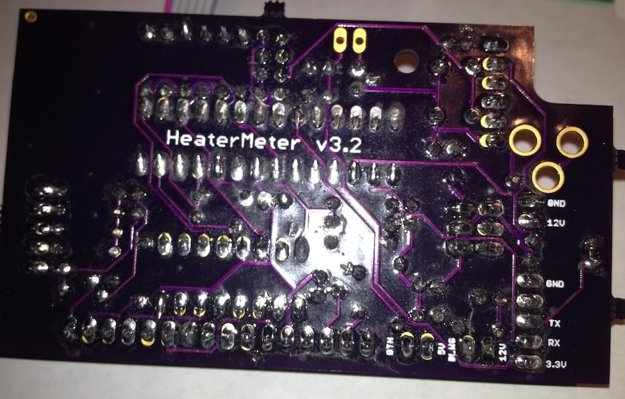
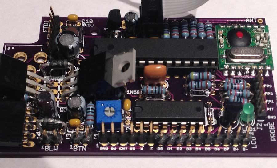
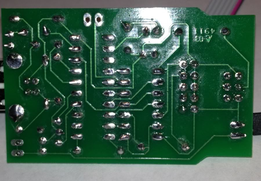
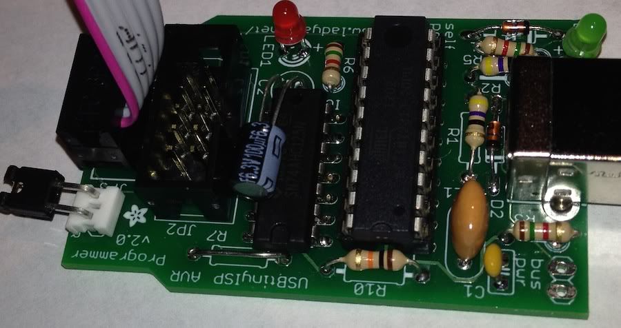
ok I got my board all soldered. I built the Tinyusb device from adafruit.

Do I have to connect the soldered board to the linksys before I flash the bootloader onto ATmega328P? I wasn't sure if the programmer powered the board enough to program the chip?

I tried connecting it directly to the board and keep getting RC=-1 error
 
Originally posted by Dennis C:
I wasn't sure if the programmer powered the board enough to program the chip?
I tried connecting it directly to the board and keep getting RC=-1 error
Yeah the USBTinyISP powers the HeaterMeter board. Make sure you've got the jumper on the the USBTinyISP (JP3, USB power to target) or else it doesn't power the target.

Other than that all I can think of is to check the orientation of the AVR and the ICSP cable at both ends?
 
Yeah the USBTinyISP powers the HeaterMeter board. Make sure you've got the jumper on the the USBTinyISP (JP3, USB power to target) or else it doesn't power the target.

Other than that all I can think of is to check the orientation of the AVR and the ICSP cable at both ends?

I do have the jumper on both pins. This isn't a spokePOV kit is it? I used wires on the Tinyusb board instead of the 1.5k
<<If you are using the UsbtinyISP with a SpokePOV kit, install R4 and R7 (1.5K) as well. If not you may want to switch these resistors for jumpers (see the second photo for a 'finished' shot) as it will mean that target boards with loaded pins can be programmed.>>

The Tinyusb has a green light on it as well

I'm on a Mac. I was using avrdude

avrdude -c usbtiny -p ATmega328P -U flash:w:heatermeter.cpp.hex

Does that look right? I'm new to mac OS.
 
Originally posted by Dennis C:
I do have the jumper on both pins. This isn't a spokePOV kit is it? I used wires on the Tinyusb board instead of the 1.5k

avrdude -c usbtiny -p ATmega328P -U flash:w:heatermeter.cpp.hex
Yeah my USBtinyISP also uses the wires. I use the Arduino IDE to burn the bootloader rather than avrdude because I can never figure out what the right commands are. In Arduino, make sure you select the board (Arduino Uno) and programmer (USBtinyISP) and then select "burn bootloader".

If you decide to stick with getting avrdude to work, you want to flash optiboot's hex file, not the heatermeter hex. HeaterMeter is loaded via optiboot.

I am going to try it on my windows machine. Thanks for the Tip on using hte Arduino IDE maybe I will give that a shot
 
Originally posted by Bryan Mayland:
<BLOCKQUOTE class="ip-ubbcode-quote"><div class="ip-ubbcode-quote-title">quote:</div><div class="ip-ubbcode-quote-content">Originally posted by Dennis C:
I do have the jumper on both pins. This isn't a spokePOV kit is it? I used wires on the Tinyusb board instead of the 1.5k

avrdude -c usbtiny -p ATmega328P -U flash:w:heatermeter.cpp.hex

I noticed I am missing the /dev/tty.usbmodem621 or any USB type choices in my serial port choices. On the windows machine the Serial port options are greyed out?
Yeah my USBtinyISP also uses the wires. I use the Arduino IDE to burn the bootloader rather than avrdude because I can never figure out what the right commands are. In Arduino, make sure you select the board (Arduino Uno) and programmer (USBtinyISP) and then select "burn bootloader".

If you decide to stick with getting avrdude to work, you want to flash optiboot's hex file, not the heatermeter hex. HeaterMeter is loaded via optiboot. </div></BLOCKQUOTE>
 
Originally posted by Dennis C:
I noticed I am missing the /dev/tty.usbmodem621 or any USB type choices in my serial port choices. On the windows machine the Serial port options are greyed out?
Yeah on Windows there is no indication that the USBtinyISP is plugged in at all. If you have the right programmer selected and burn bootloader, it will say "Can't find USB device 0xXX/0xYY" if the driver isn't installed properly or an error code if it was found and couldn't talk to the chip.
 
Still getting the RC=-1 error. Not sure what to do next at this point. I checked all my solder points and everything looks good.
 
I probably have to assume it is the tinyusb that is not working correctly? Back on my Mac OS I did a ls -l /dev/cu.* and usbserial didn't even show up or anything as a device connected.

I can get the green light to light up and the red blinks when it errors but nothing else happens
 
It won't show up as a serial device because it's an actual USB device not a serial emulator. I don't know what it could be. Somewhere between the ATtiny in the ISP and the ATmega in the HeaterMeter. Maybe post a couple pictures with it hooked up we can take a look at it?
 
Originally posted by Dennis C:
IMG_0479.jpg
Hey you did the same thing I did when I built mine, connect the LEDs too close so they don't poke out of the case right!

Here's your problem though. Pin 1, as you know is the one with the red stripe, but it is actually on the other side of the connector, i.e. the side that doesn't have wire coming out of it. Take your cable off and swap it with the other end so it ends up like this
 
Tried that several times. still having the same problem :-( Thanks so much for tip not he wires. Didn't realize they were directional.

So odd.
 
I recieved my boards from Dork bot and soldered up all 3. I already had my Atmega ready to from my original heatermeter and I put it on then i hooked up the 12 volt power to the board and the connectors to the router, that I had been using for the last year with the heatermeter.

Well now I ruined my atmega chip and router.

The boards are at the j7 connector are kinda confusing as it has the pow right next to the Gnd connector, which is 2 on the board and the J7 is next to the 12volt power connector 1
icon_frown.gif
.

Luckly I bought like 7 of the routers over a year ago, lol. And I had one extra V3.1 that still worked.

I will give it another go after I get some parts from Pololu.
 
Originally posted by Jason Allen:
Anyone have an extra v3.2 PCB they want to sell?

Or anyone placing an Dorkbot order soon that I could tack onto?

Jason I had bought three of the boards. I can sell one of them. Paid 28 dollars for the three of them shipped so just figure 10.00 shipped.

Email me at nydennis@yahoo.com if interested (this is not a primary email address for me so I don't care that it is public)
 
Originally posted by Dennis C:
Tried that several times. still having the same problem :-( Thanks so much for tip not he wires. Didn't realize they were directional.
I'm sorry but I've stared at your boards for 15 minutes now trying to see if I can find something else wrong with them, but they look good with all the parts facing the right direction and everything. I'm really at a loss as to why it wouldn't work.


Back
Top