HeaterMeter Hardware v4.2.4


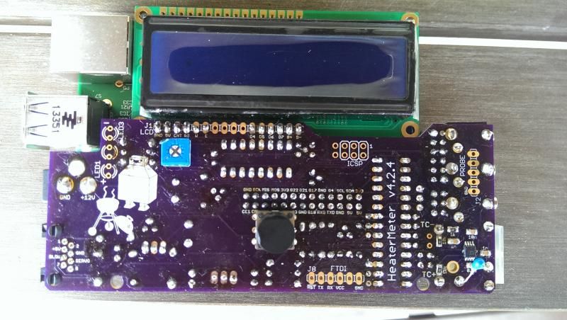
The AVR firmware isn't flashed onto the chip until the Pi boots fully the first time with the HeaterMeter attached. It just looks dead up to that point. Does the Raspberry Pi boot? You should see the activity light on it blink as soon as power is applied, then blink a lot for about 10 seconds. Full first boot takes maybe a minute.

If that's working, time to bust out the multimeter
 
Thank you Bryan! Yes, Raspberi pi comes on just like u said. I've seen this chart before and funny how I didn't think of it. Thanks for the direction. Yes Ralph, I've adjusted contrast. Time to check with the multimeter now. Never done that before. I'll YouTube it and start with the voltages. Any suggestions when trying to find the bad circuit?
 
First off, you might try removing the ATMega from the socket then retouch the soldering on it's socket, then reinstall the chip and inspect the solder joints for bridges etc with a magnifying glass or zoomed in on a digital picture. Boot the unit once again with the rPi and give it a couple minutes for the rPi to boot, detect and flash the ATMega. Also, to confirm your rPi is booting and loading the OS you can plug in a monitor (or tv) to the HDMI output on the rPi, watch the screen to see the boot progress. If the rPi boots properly and loads the linkmeter system then you can try (via USB keyboard) to manually flash the AVR using the command avrupdate /lib/firmware/hm.hex
If all that fails you should poke around on the board using the reference Bryan provided trying to find a point where the voltages are not proper (too high, too low, absent), if you locate an improper voltage that may help lead you to the area where there is a problem....
Have you checked the orientation of all your electrolytic caps, diodes and transistors? If you post high res pictures of the top and bottom of your board forum members can give them a look over and see if they can find something out of place....
 
8


Ralph, I did what you said and retouched the soldering joints on the ATMega socket...no luck. I then hooked up the rPi to the HDMI and it booted up so I know it is working. I tried to flash the command avrupdate /lib/firmware/hm.hex but it didnt seam like anything happened (don't know the proper command prompts). I shot some pics of my board after making sure the transistors, caps and diodes looked the same. I triple checked all the resistors when soldering to make sure they were the correct ones, but maybe you or someone else could glance at them for me. I have several more pics I can post if this one turns out ok. My UDS is patiently waiting to get fired up. Thank you for all your anticipated help.
 
I'd start by checking the "FTDI" connector. Is there 3.3V between VCC and GND there? If so check the ATmega pin 1 - bottom left by the H in HeaterMeter, should be 3.3V as well. If both of those are good then the output of `avrupdate` might be interesting. Just snap a photo of your monitor. It should show something like this (although not because like you said it isn't working)
Code:
root@OpenWrt:~# avrupdate
Stopping LinkMeter OK

LinkMeter platform is BCM2708
Loading SPI modules...
AVR fuses ffd705 OK

Starting LinkMeter OK

Do you have a thermistor attached to the pit jack down there? While that doesn't hurt, it doesn't do anything either. The thermistor can only be connected like that to a probe jack with the 2.5mm jack, because it si the jack it self that completes the circuit for when nothing is plugged in.
 
Thank you Bryan. I checked between VCC and GND and it's showing 0.03V on my multimeter set at 20. Also, the ATmega pin 1 shows 0.03V, the same. I assume one of the capacitors in wrong? I checked a few and found 2 of the 0.01u were not reading, possibly bad. I can not find a full bare pic showing the bottom part of the board without capacitors. I would like to make sure the Ohms are accurate. I plan on removing any bad ones and replacing, hoping that does the trick unless you got any suggestions beforehand. My monitor after plugging in says:

root@OpenWrt:~# avrupdate
Stopping LinkMeter OK

Linkmeter platform is BCM2708
AVR fuses ERROR

Starting Linkmeter OK
 
Errrr I'm not familiar with your multimeter but 0.03V seems not right. You may want to measure the 3 legs of the regular MCP1700, there should be 5V on the solo middle pin, 3.3V on one pin, and GND on the other. Your capacitors almost certainly aren't bad. I'm not sure how you're testing them but you can't test capacitance in-circuit.
 
Jason, Capacitors are not measured in OHMS, their units are FARADS. You can not check them by measuring resistance, they need to be checked with a special capacitor checker or multimeter that has a capacitor function, and generally needs to be done out of circuit to get a good measurement.
Here is a pic of my HMv4.2.3 board I shot before I built it up, the capacitor values and positions should be the same as the HMv4.2.4:
HMv4.2.3BoardTop.jpg


That said, reading the output you posted I think caps are not your problem, the part that says AVR FUSES: ERROR is what concerns me. Recently someone else came accross this issue with an ATMega that was not a standard blank unit and had to do something to manually reset those AVR fuses before he could flash it. Bryan set him up with the info he needed, I am sure he will help you, or you could locate that thread and follow the advise he gave the other fellow.... and BTW, it's best to start your own thread about a problem when you need help, rather than posting in the sticky thread about the HM hardware...
 
Errrr I'm not familiar with your multimeter but 0.03V seems not right. You may want to measure the 3 legs of the regular MCP1700, there should be 5V on the solo middle pin, 3.3V on one pin, and GND on the other. Your capacitors almost certainly aren't bad. I'm not sure how you're testing them but you can't test capacitance in-circuit.

What about the AVR FUSE ERROR Bryan?
 
I got it!!! Thank you guys so much. It was my fault. I went back and looked at the Signal MOSFETs and 3.3V regulator. When I ordered the parts I got 4: MCP1700-33's (IC4) and 4:BS170's (Q1,2,4,5) because of the Mouser project list was a little off at that time. It's been corrected and I used the 4 MCP1700-33's in the BS170 spots. I guess I have to mess up to learn from my mistakes. I can say I am much better at soldering now than when I started out. I really appreciate you Bryan and Ralph for helping me! Sorry for all the issues. :)
 
Thank you Bryan. I checked between VCC and GND and it's showing 0.03V on my multimeter set at 20. Also, the ATmega pin 1 shows 0.03V, the same. I assume one of the capacitors in wrong? I checked a few and found 2 of the 0.01u were not reading, possibly bad. I can not find a full bare pic showing the bottom part of the board without capacitors. I would like to make sure the Ohms are accurate. I plan on removing any bad ones and replacing, hoping that does the trick unless you got any suggestions beforehand. My monitor after plugging in says:

root@OpenWrt:~# avrupdate
Stopping LinkMeter OK

Linkmeter platform is BCM2708
AVR fuses ERROR

Starting Linkmeter OK

I too got distracted by the talk about capacitors (if they are the right value in the right orientation I'm 99.9% sure they are NOT the problem!)

You can't run a board with VCC of zero, so you are either measuring the wrong spot or have your meter set wrong or something. VCC for this chip should be 3.3v, not 0.03, so maybe you are just reading it wrong?

The power supply in the HM goes like this... 12VDC in from wall wart, the DC-DC converter IC1 reduces that down the 5VDC, then Voltage Regulator IC4 reduces that down to 3.3VDC. So, to check your power first measure 12VDC at the input, if you read 12VDC there you know you have your meter working right... Then check IC1 for an input of 12VDC (or same as source, may be a bit higher depending on your wall wart) and output of 5VDC, then check IC4 for an input of 5VDC and output of 3.3VDC. If you are not seeing proper voltages then look for a short or bad solder in that section, check the orientation of capacitors and diodes (diodes were obscured in your pictures) etc.
 
I got it!!! Thank you guys so much. It was my fault. I went back and looked at the Signal MOSFETs and 3.3V regulator. When I ordered the parts I got 4: MCP1700-33's (IC4) and 4:BS170's (Q1,2,4,5) because of the Mouser project list was a little off at that time. It's been corrected and I used the 4 MCP1700-33's in the BS170 spots. I guess I have to mess up to learn from my mistakes. I can say I am much better at soldering now than when I started out. I really appreciate you Bryan and Ralph for helping me! Sorry for all the issues. :)

Glad you got it working! I had just posted a run down of the HM power scheme, I had kinda just assumed you had something hokey going on with your meter... I guess since there was that little mix up with the Mouser cart for a while the first suggestion when a new build doesn't power up should be "what component do you have in the IC4 position"....
 
I got it!!! Thank you guys so much. It was my fault. I went back and looked at the Signal MOSFETs and 3.3V regulator. When I ordered the parts I got 4: MCP1700-33's (IC4) and 4:BS170's (Q1,2,4,5) because of the Mouser project list was a little off at that time. It's been corrected and I used the 4 MCP1700-33's in the BS170 spots.
Huzzah! I swear, that copy-paste mouser project error will never stop haunting us. I tried to zoom in and see if the MCP1700 had the wrong part in it on your photos but it was blocked by the capacitor so I figured it must be working (because the normal behavior is that it browns out the 5V supply too). Good work sticking with it and figuring it out!
 
Bryan,

From what I can tell, this mouser part looks like it should be drop-in fit for the female header used to mate the RasPi, which is listed as a digikey only item on the hardware list.

Mouser Part: 649-66953-013LF

I'm trying to avoid spending $8 shipping for each site. It would be nice to be able to purchase all of the parts from 1 place.
 
It's actually listed with an alternate mouser part, which is slightly different. This does look like it would fit better, but geez $4.12. I'll get one on the next order and find out though. You're still screwed on the 2.5mm jacks being digikey only.

I've already gotten some 2.5mm jacks which may be the go-to jack for the next version. They're not at all the same footprint, and don't have the break pin so any ambient thermistor would have to plugged in externally.
 
Bryan, I've gotten panel mount 2.5mm jacks from both mouser and digikey for the roto damper. The last bunch I got from Mouser. I see no reason why they couldn't be used on the HM, just remove the panel mount nut and it should be good to go. These DO NOT look like the picture shown on the Mouser page, click the datasheet and you will see the actual profile of the part. This one does have the third switched leg on it like the ones you have been using from Digikey (the info on the Mouser page is way wrong, the datasheet is correct)
 
Well that's another option for sure then, thanks Ralph!

I would much prefer to see you use that 2.5mm jack with the switch, 'cause not only does it facilitate the wiring of the ambient temperature thermistor, I also use the third leg to wire in the probes from my CAT5 jack. It's nice to have the switch so you can use a direct wired thermistor/probe OR plug a probe into the HM jack and have that one work instead....


Back
Top