Originally posted by Bryan Mayland:
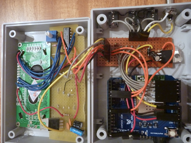
Here's the guts of the version I built for my dad, to give you guys another idea of how the layout can be.
The main Arduino/WiFi connects to the board next to it that handles all the probes and fan. A plug from that goes up to the LCD/Shift Register/Buttons in the lid.
There's also the extra 5V regulator up there, so the Vin comes from the Arduino, up through the WiFi shield, over to the sensor board, up to the lid, is converted to 5V which is then piped to all the components up there, down to the sensor board then fed back to the Arduino via the ARef pin. The 5V lines from the Arduino are cut so they don't power anything but the mainboard itself.
Putting the probe and fan jacks on the right side of the device rather than in the front made it a lot easier to space them out than the original design, although in this one the project box comes about 2mm from closing due to the extra height from the extra stuff in the lid and the fancy connectors I used for the Arduino mating connectors.