Version 2 of my homebrew controller


Here's another tip. Don't try to use a ArduinoPro 5V from Sparkfun for this project. The voltage regulator is only rated for 150mA and the LCD can draw 100mA and the WiFi draws 230mA when transmitting. I just built a whole system with it and with just the arduino and the wifi connected, it reboots every 20-30 seconds. I'm having to add my own LM7805 to provide 5V for the wifi and let me tell you this is just a pain in the ***.
 
Good advice Bryan, thanks again for all you have contributed. I have been playing around with trying to get your code to work on a yellowjacket with no luck. I assume it's trying to use the flash module that isn't there and locking up but who knows. Can you give me some pointers how to disable the flash's use? I know it's web serving capabilities are limited but I'd love to build the yellowjacket into a tiny fan controller for a friend of mine.
 
Can you give me some pointers how to disable the flash's use?
Yeah if you just want to see if it runs, look near the bottom of the main file, in the setup() function. There's a line that says dflash.init() or something like that. Comment that out and it won't try to use it unless you send it a web URL that isn't one of the dynamic ones (/csv or /json or a settter).

If you want to get rid of that too, look at the bottom of the page serve function and just comment out the last else case where it searches for pages in dataflash.
 
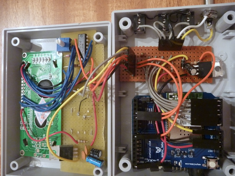
Here's the guts of the version I built for my dad, to give you guys another idea of how the layout can be.
implementation2-1.jpg

The main Arduino/WiFi connects to the board next to it that handles all the probes and fan. A plug from that goes up to the LCD/Shift Register/Buttons in the lid.

There's also the extra 5V regulator up there, so the Vin comes from the Arduino, up through the WiFi shield, over to the sensor board, up to the lid, is converted to 5V which is then piped to all the components up there, down to the sensor board then fed back to the Arduino via the ARef pin. The 5V lines from the Arduino are cut so they don't power anything but the mainboard itself.

Putting the probe and fan jacks on the right side of the device rather than in the front made it a lot easier to space them out than the original design, although in this one the project box comes about 2mm from closing due to the extra height from the extra stuff in the lid and the fancy connectors I used for the Arduino mating connectors.
 
Originally posted by Bryan Mayland:
Here's the guts of the version I built for my dad, to give you guys another idea of how the layout can be.

The main Arduino/WiFi connects to the board next to it that handles all the probes and fan. A plug from that goes up to the LCD/Shift Register/Buttons in the lid.

There's also the extra 5V regulator up there, so the Vin comes from the Arduino, up through the WiFi shield, over to the sensor board, up to the lid, is converted to 5V which is then piped to all the components up there, down to the sensor board then fed back to the Arduino via the ARef pin. The 5V lines from the Arduino are cut so they don't power anything but the mainboard itself.

Putting the probe and fan jacks on the right side of the device rather than in the front made it a lot easier to space them out than the original design, although in this one the project box comes about 2mm from closing due to the extra height from the extra stuff in the lid and the fancy connectors I used for the Arduino mating connectors.

Very nice Bryan! Thanks once again for sharing the detail.

- John
 
Originally posted by Ed Pinnell:
...numbers are the same for the BC2444-ND, so I'm not sure why Bryan made the change.
Aw **** did we already have a replacement part for the Radio Shack one? I must have missed that so I just went looking for other 10k ohm thermistors.

That's pretty **** cool how you set up your unknown probes, I never would have thought about that!
 
Originally posted by Bryan Mayland:
<BLOCKQUOTE class="ip-ubbcode-quote"><div class="ip-ubbcode-quote-title">quote:</div><div class="ip-ubbcode-quote-content">Can you give me some pointers how to disable the flash's use?
Yeah if you just want to see if it runs, look near the bottom of the main file, in the setup() function. There's a line that says dflash.init() or something like that. Comment that out and it won't try to use it unless you send it a web URL that isn't one of the dynamic ones (/csv or /json or a settter).

If you want to get rid of that too, look at the bottom of the page serve function and just comment out the last else case where it searches for pages in dataflash. </div></BLOCKQUOTE>

Thanks Bryan. I'll give it a try this evening.
 
Originally posted by Ed Pinnell:
BUT...there is a lot of rounding of the resistance values in the meter that I was using and it occurred to me in my sleep that maybe I could get the HeaterMeter to log it more accurately than I can do by hand, which it does very nicely, although I think it could be made even more accurate than my crude attempts at programming by some talented young man such as yourself...perhaps even to the degree that the HM could become self-calibrating.

I've been wanting to ask you: Can you return that rt-n12? If I may be so bold as to offer an unsolicited opinion, I really think you will be much happier with something that offers external storage (USB/MMC/SD)...
I've actually found a better coefficient-generating application, which draws graphs and will generate lookup tables if you want them. Application Note AN2395 Thermistor Lookup Table Generation Tool. It would be nice to let HM do all the math for you in a special calibration mode, but there's certainly not progmem room for it on the WiFi version. I'm not even sure how long it would take to do least square error sum curve fitting on a 16MHz 8bit CPU with no FPU.

I ended up not getting the RT-N12 because I missed the rebate on it and wasn't going to spend $40 on it. I did end up getting an RT-G32 for $12 instead, but it also has 4MB of storage. I'll see what I can fit in that first and if I have to get something with external storage so be it.
 
I think the main reasons I got it over a WRT54GL were availability, cost, and aesthetics. Yeah that's right, I hate how those old Linksys boxes look. This probably stems from when our office was outfitted with Linksys WAP11 access points (802.11b) in 2001 which look identical. Half of them became of questionable reliability after a few months and for some reason everyone in a 10m radius would come to me for help when they had wireless issues. Just plug the wired ethernet in, I'm not the Help Desk! (RAGE)

I got the "g" version, not the "n" one. I only popped it open briefly and it doesn't look to have JTAG, just serial. I've restored ASUS routers over serial before so we'll see how that works. I agree about the limited write cycle problem, which is why I probably won't be keeping a complete log file. I'm considering an in-memory RRD that's synced to flash every -Interval- maybe? I'm not sure yet. I really just wanted a low cost-of-entry test system to play with and see what could be done.
 
Bryan / Ed,

As you know, I'm working on a Instructable to document this project. I haven't touched my half-built controller since just before Thanksgiving due to a hectic schedule at home and work. I hope to get back going on it this weekend.

With that said, I'm considering finishing the Instructable article without having completed the project myself yet. You guys would need to be the source for completed photos of the device in operation, etc. I'm initially basing this on Bryan's version that we all started building (with the parts list that I worked up in Google Docs).

Before I do this I wanted to check to see if you guys are OK with this approach. As originally planned, I'll certainly give credit where credit is due in the article. I'll also need permission from Bryan to attach the code for distribution in the article.

Anyway, let me know if this is OK. I may also try to get it entered into one of the Instructable contests before the weekend ends. Feel free to contact me via email for further discussion on the topic if desired (siliconghost at gmail).

Thanks!

- John
 
Originally posted by John Mangan:
Bryan / Ed,

As you know, I'm working on a Instructable to document this project. I haven't touched my half-built controller since just before Thanksgiving due to a hectic schedule at home and work. I hope to get back going on it this weekend.

With that said, I'm considering finishing the Instructable article without having completed the project myself yet. You guys would need to be the source for completed photos of the device in operation, etc. I'm initially basing this on Bryan's version that we all started building (with the parts list that I worked up in Google Docs).

Before I do this I wanted to check to see if you guys are OK with this approach. As originally planned, I'll certainly give credit where credit is due in the article. I'll also need permission from Bryan to attach the code for distribution in the article.

Anyway, let me know if this is OK. I may also try to get it entered into one of the Instructable contests before the weekend ends. Feel free to contact me via email for further discussion on the topic if desired (siliconghost at gmail).

Thanks!

- John

John, Thank you for taking this on, if I can be of any help with pictures, verbiage, or proofing, please let me know.
 
Ed ~ about the lull.... Waiting for "Free Day" Jan 13. Love the router build BTW. I'm thinking about getting the new Mega for $60. Lots of memory there.

-rob
 
Hello just finishing my first take on Bob's controller.

Very much stock to his schema and code so no changes.

I am using a 12v wall mart to power the fan and arduino at the same time.

I am using the BlackWidow 1.0

http://asynclabs.com/store?pag...egory_id=11&vmcchk=1

Couple of questions:

1) Will I fry the main board if I leave the power plugged in to the internal plug and then plug in the USB?

2) When I don't power the arduino from the wall mart, but power from the USB connection, when I grab the temp probe in my hand I see the temp correctly change, and if I have the set point @ 85 it will turn off the fan. But when I am powered only by the wal mart, the power and temps jump very randomly, fan going to 100% down to nothing.

Now if I don't touch the probe and use a heat gun to raise the temp, it works correctly just like plugged into the USB connection.

Any suggestions would be appreciated.

Thanks,

Kevin
 
1) I know with a standard Arduino you can have them both plugged in and it will use the power off the wall adapter and feed back into the USB port. It looks like the BlackWidow has a similar circuit in the schematic (look at the top left with the two OpAmps and P-Channel FET), with the FET acting as the diode.

2) I had a similar problem when I was doing my solderless breadboard trials, where it seemed me touching the probe would change the resistance. All I can say is that the issue went away when I built the soldered version, even if I touch probes to each other or put them in my mouth.
 
First of all, let me say WOW! There are some amazing things in this thread! I'll get to my question first, and provide more information and background after, for those interested.

Would someone mind providing a physical explanation of how I would wire the Maverick probes into this system, specifically based off Bob's original schematic and as if I were just using a breadboard? I think if I know how it works on a breadboard, I can take it from there. I will be glad to provide an email address if someone would prefer to send it to me directly instead of using space in this thread for such a beginner question.

I'm an all around geek and can handle the code part of this no problem. But when it comes to reading Bob's electrical schematic, there are a few mental hang ups I'm running into. I spent a good 3-4 hours Friday looking at the many pictures on this thread, another one at the Arduino forums and Bob's page trying to figure out the wiring myself (and while I was waiting for membership approval here), but I just can't quite piece it together.

I really want to build this project, but I've yet to purchase any parts due to my lack of experience with translating a schematic into real-life circuitry. I want to make sure I understand everything first before I pull the trigger on the parts.

My goal is to make something like Bob's design, minus the LCD screen. I also plan to use a blower as described in Bob's plans and to hook it up to an offset.

Sorry for the long post about such a beginner topic. Any insight provided will be VERY appreciated and will help me on my path of learning and discovery!
 
Thanks for the response, Ed!

I have read this entire thread and tried to understand as much as I could. I will follow Bryan's advice regarding WiShield 2.0.

Let me share what I think the correct route to follow is, regarding the probe circuitry. I ask for forgiveness beforehand, as this will likely sound unintelligent and incoherent.
icon_biggrin.gif


On the breadboard:
From the 5V bus, a resistor connect one of the horizontal rows, say row 15. The thermistor then connects to a spot adjacent horizontally to the resistor. The ground of the thermistor runs to the ground bus on the breadboard. The analog sensor wire, say A5 on the Arduino board, then connects to an horizontally adjacent spot on the breadboard on the same row.

Is this correct?

EDIT:
I should also add that I plan on using the 2.5mm mono jack as described. I feel I have a solid idea on how to use though.
 
Thanks again, Ed! So all of my thinking was correct. Thanks for verifying it.

Now on to my next big question: powering the 12 VDC blower. If I remember correctly, it was stated a few posts ago that I can plug a 12 VDC wall wart directly into the Arduino board and that the board will step down the power to 5V. How do I then get the 12V over to power the fan?
 
I'm going to introduce myself here too! I will be attempting a barebones version. If I can get this thing to keep a +/- 5* range from where I set it (provided enough fuel) I'll be a happy camper.

I got in on Free Day and I've got an Arduino Uno, LCD, and buttons coming. Also plugged in the parts of that spreadsheet into digikey and have that stuff coming.

I need to order one of the smoker probes and sit back until everything comes in. Mine won't have web functionality and it won't monitor ambient temp or food temps, it will be strictly
one smoker temp input, the IC (with buttons for config) and a blower output hooked up to my egg. My cost in the end will be about $60, but that's including a $40 credit from free day.

Uno's are on backorder so it may be awhile before I'm able to begin, but I've been reading this thread in the mean time and I've even found my old IC/TTL books from school in case I need them.


Back
Top