Servo Booster...


It is just like the schematic that Peter F posted but because it is unidirectional you only need the resistor on the 5V side. So the center pin goes to 3.3V, the "source" pin goes to the ATmega side (labeled GPIO in the image), and the "drain" pin (labeled 5V logic) needs a 1k pullup to 5V (10k is too weak) and that goes to the servo.

But yeah don't use the schematic I sent you for the boost circuit, that's hooked up wrong
 
Oh, damn, that means I can't just make an easy inline version of this for in/out testing since it needs the +3.3v which is not present in my CAT5 jack.... In that case I guess I will just wait until I have the HMv4.2 board, cause I don't feel like doing any surgery on my HM that's buttoned down in the case right now....

Edit: well, I guess I could use a 3.3v regulator as well as the MOSFET to make an inline version for testing... I'd kinda like to be able to plug it in and out to compare when testing.
 
Last edited:
Yeah I'd just say wait. It is really easy to test on the v4.2 board I sent you. Just test the MOSFET version first because otherwise you've got to remove the 10k resistor, which makes it slightly less easy.
 
Is this the circuit I should be building to test the MOSFET servo booster?
MOSFETBooster.jpg


I just built up an inline version of that circuit using a MCP1700-33 to provide the 3.3v and it doesnt seem to work. The servo doesnt move at all. Well, I did hear it move when I first plugged it in but it does not move when the HM tells it to. Also, the probes don't register when I plug it in either, though they do register when I plug in my BC337 booster (which works great for me BTW).
I checked continuity for the probe leads, verified the ground and +5v on the regulator, the 3.3v ends up at 2.86V for some reason but is present. All wiring is good, did I make a mistake with the circuit?
 
Last edited:
Yeah you've definitely got something wrong if your 3.3V is putting out 2.86V. There's something shorting to something because the 3.3V supply has 0 current on it at all times (aside from leakage) and therefore shouldn't be struggling to regulate. You don't have something hooked up backwards do you? I can tell you that when I build this circuit I see 3.3V at the gate, and ~4.8V signal at the drain (well when it is signaled).
 
Well, I've checked the pinout for the MOSFET and the regulator a few times and seem to have the circuit wired correctly, and have inspected with a magnifying glass to confirm I don't have any shorts... So I'm not sure why its not working or why I have only 2.86V on the output of the 3.3v regulator... I guess maybe I burned one of the components up while soldering it or something....
The HMv4.2 board should be delivered tomorrow so I guess I will wait and try the circuit again on the board.....
 
Is this the circuit I should be building to test the MOSFET servo booster?
MOSFETBooster.jpg


I just built up an inline version of that circuit using a MCP1700-33 to provide the 3.3v and it doesnt seem to work. The servo doesnt move at all. Well, I did hear it move when I first plugged it in but it does not move when the HM tells it to. Also, the probes don't register when I plug it in either, though they do register when I plug in my BC337 booster (which works great for me BTW).
I checked continuity for the probe leads, verified the ground and +5v on the regulator, the 3.3v ends up at 2.86V for some reason but is present. All wiring is good, did I make a mistake with the circuit?

What's the input voltage on S "IN From HM"? That's the voltage you should see on the (D)rain when the gate is triggered and causes S and D to connect.
 
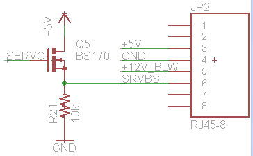
Bryan, I am confused about your MOSFET booster circuit, if you could clarify the circuit for me I would appreciate it...

The HMv4.2.3 schematic I have shows this:
MOSFETBooster2.jpg


The above is identical to my NPN booster circuit only substituting MOSFET for NPN.

The MOSFET circuit we discussed here was:
MOSFETBooster.jpg


This one has 3.3v on the grid, and the resistor on the output goes to +5v (instead of ground as shown on the 4.2.3 schematic and in my NPN circuit)

As you know, the MOSFET circuit on the HMv4.2.3 board seemed to be working (wired as shown in the first image as found on the 4.2.3 board), but the servo started flaking out a bit when I started using a larger blower, however, when I put my NPN booster inline the twitching went away.

So, I am trying to suss out exactly what the proper MOSFET circuit should be? I moved the resistor on the output over from ground to +5V, the servo is lifeless when connected like this. Do I also have to lift the +5V from the MOSFET grid and feed it 3.3v instead? (as shown in the second image?)

I don't have a 4.2.4 schematic to reference so I am at a loss.....
 
OK, got the proper MOSFET circuit wired up (second image in my above post) and it is working fine with the large blower....


Back
Top