Servo Booster...


RalphTrimble

TVWBB Diamond Member
I had improperly posted this topic in the development log for discussion, I have made some initial findings so I decided to post a fresh thread here...

I have been experiencing some crazy servo behavior when running the servo over a very long CAT5 cable (~50ft I would guess). The servo would spasm rapidly at times, the longer the cable the more likely it would happen. Doing some reading up on servos I found that there isn't much room for error in the signal when you run a 3.3v controller (our ATMega) with a 5v servo, it is much better to match the control line voltage to the servo voltage. In some cases a servo booster circuit is used to overcome this sort of problem.

I looked up some servo booster circuits and decided to test the most simple form, using one NPN transistor and a 10K resistor. Since I have in stock extra BC337 transistors from my HM build as well as 10K resistors I decided to give these parts a go.

Here is a diagram of the very simple circuit I am testing:
ServoBoosterCircuit.jpg


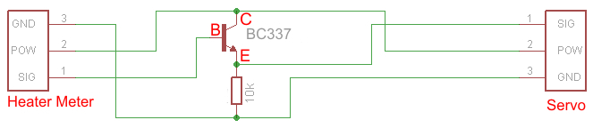
Here is a picture of the actual components:
ServoBooster.jpg


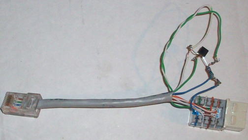
Initial tests went really well. When I run the servo over the long cable the servo goes nuts, after I insert the booster inline the servo is rock solid!

Here is a video of the test. I start out with no booster and the problem will be obvious, then I insert the booster and the problem goes away. While the booster is installed I move the servo up and down in 5% increments a bit, then in 1% increments, finally I remove the booster for the last few seconds of the video. Movement is nice and solid and accurate with the booster, not so much without.

This simple booster solved my problem with the long cable run, haven't tested the limits of how long a run will work, but this is definitely a big improvement. If there is room on the HM board for one more transistor and a resistor it would be nice if this booster could be included in the next build.
 
Last edited:
im glad it worked, but I would have to say that there would not be to many people running 20+feet of cable from there HM to the servo. I understand you want to be able to stay inside to check the HM from time to time but that's what the internet part of the HM is for. I have had my HM in Snow, Thunderstorms ect.... without fail.

if there is room on the HM for I would be in favor, if not the booster is easy to make and or cheap to buy(3 dollars)
 
In my test I used the booster on the source at the HM, not sure if it would work as well on the servo end after the signal is degraded (I will have to test that but we've got a heavy downpour going on here right now). To add at the source end is harder now that the CAT5 jack is onboard, you would have to cut the trace and insert the booster there. I had asked Bryan in the other thread to at least include an easily cutable trace for the servo signal lead, but I think one more BC337 on board isn't a big deal?... or I guess you could cut into or make a custom cable with the booster in it..

I know the long cable might sound crazy, but its really nice to have the HM safe in the kitchen when the massive wind and rainstorm hits, or when snow is coming down in piles. I have gotten pm's from a few other folks in the northern regions asking how long the cable can be 'cause they would like to do the same. In addition to that, I think some of the servo chatter people are experiencing while using shorter cables might be due to signal loss/rejection due to the 3v/5v thing, and this would cure that too. From what I read about servo's in other forums they talk about adding a booster on a 3v/5v setup when cables get as long as 24 INCHES...

That said, I am happy to have figured it out and solved it for myself, if need be I can certainly modify my HM's with the extra 20 cent transistor...
 
I don't live far from ya, lol. We get the same weather. I have been more worried about the blower giving out then the HM in weather.
64j9eo.jpg
 
I know we don't see eye to eye on the issue, I like to have the ability to run my HM inside rather than out in that mess. This mod has given me the ability to do so more reliably and further if need be, all for the cost of a 20 cent transistor...

The long CAT5 cable is also useful when doing remote cooks, like camping, so you don't have to pull AC power out to the pit location, the pit can sit at the end of the CAT5 cable while the HM sits near the power source. Or perhaps run the HM from the cigarette lighter in your car with the pit on at the end of a long CAT5 cable...
 
Last edited:
You could just print a small housing for two cat5 jacks and the booster components and make a simple inline coupler booster.
 
Wow that servo is a mess without the booster! Nice work on finding a fix and I'll see what I can do about integrating it.
 
Interesting. It appears that the servo signal is driven directly off the ATmega 328P, and your addition of an NPN raises the signal level. What's the voltage output off the pin on the ATmega that drives the servo? Is it just an issue of low voltage getting squashed by the long cable run (i.e. high resistance)?
 
Wow that servo is a mess without the booster! Nice work on finding a fix and I'll see what I can do about integrating it.

Cool, I appreciate you considering it. Initially I had thought it might be interference in the wire from the blower switching as you had suggested, but recently I have been running without the blower and noticed the behavior and realized it couldn't be that. If you notice in the video, when the servo hits 100% the blower kicks on and all is good...

So that led me to research a bit about servo's and I came up with the info about the 3v/5v situation and signal rejection. When I read the thread about others having problems controlling servo's with a 3.3v Arduino I just knew this had to be it. I was really surprised this simple circuit fixed it up so well!

Looking at the HM schematic I was kinda surprised to see the servo signal lead attached directly to the ATMega, though I shouldn't have been 'cause I had to hard wire my servo to that pin on the Mega (on my HMv4.0). I just figured there should be some sort of buffer/driver circuit between the ATMega and the servo, I think this does a nice job and certainly is simple enough. I think we will get stronger servo behavior with this circuit in place.
 
Last edited:
Interesting. It appears that the servo signal is driven directly off the ATmega 328P, and your addition of an NPN raises the signal level. What's the voltage output off the pin on the ATmega that drives the servo? Is it just an issue of low voltage getting squashed by the long cable run (i.e. high resistance)?

The ATMega is a 3.3v chip, so it is putting out 3.3v, the servo is running on 5v and there lies the rub. If you read the info on this page it explains about servo signals and why it is best to run the servo and the controller (our ATMega) at the same voltage to avoid signal rejection/errors. They are selling inline boosters that do the same thing, only problem is we need to insert that booster at the Heater Meter end before the CAT5 jack, now that it is onboard that is more difficult.

As for the cause of the issue, I think having a 3v signal and a 5v servo puts the signal down low near the rejection point so a small amount of resistance in the wire and connectors coupled with some interference from the blower pulse and shared ground wire in the CAT5 cable can push it over the edge. With the signal up at 5V there is much more room for signal loss so the circuit is much more capable of overcoming the resistance and interference. I think this may also help eliminate some of the servo chatter that some have experience as well..
 
Last edited:
I'm am going get one of the boosters to give it a try to see if it helps on the chatter I see. It works fine in open/close setting, but when it's in % mode it chatters at different percentage.
 
The ATMega is a 3.3v chip, so it is putting out 3.3v, the servo is running on 5v and there lies the rub. If you read the info on this page it explains about servo signals and why it is best to run the servo and the controller (our ATMega) at the same voltage to avoid signal rejection/errors. They are selling inline boosters that do the same thing, only problem is we need to insert that booster at the Heater Meter end before the CAT5 jack, now that it is onboard that is more difficult.

As far as the issue, I think having a 3v signal and a 5v servo puts the signal down low near the rejection point so a small amount of resistance in the wire and connectors coupled with some interference from the blower pulse can push it over the edge. With the signal up at 5V there is much more room for signal loss so the circuit is much more capable of overcoming the resistance and interference. I think this may also help eliminate some of the servo chatter that some have experience as well..

Ah, interesting. I wonder if this could be built in place on the existing solder pads for the RJ45 on the current HM4.1 board? 5V and ground are there, you would just need to cut the servo trace and then route that from the ATmega pin to the gate on the NPN. It's not as elegant as redoing it on the PCB itself, but its kind of a cool mod.
 
I'm am going get one of the boosters to give it a try to see if it helps on the chatter I see. It works fine in open/close setting, but when it's in % mode it chatters at different percentage.

I'd be interested in your results...
With the roto damper there are a couple things (beyond this electronic situation) that can cause some chatter. First, if your servo fits too tight into the hole on the barrel it squeezes the servo and makes it kinda stiff and harder to move. If you have to force the servo into the opening you should widen the opening slightly by scraping it with a file, knife, whatever, little by little until the servo fits in there easily. Next, make sure you don't screw down the servo too tight, it should move just about as easy with the screw in place as it did when it was just press fit together. It's best to tighten the screw and then back off until the unit rotates freely as it did before you tightened it. The screw wont come out even if it is a little loose cause nothing is rotating around it. Finally, the way I have the blower rigged on mine the wires are a bit stiff, depending on the position the wire may exert some force against the servo wanting to push it out of position, the servo chatters a bit when pushing back against the force of the wire. That said, my roto damper has been pretty much chatter free lately since I figured out the above issues, at least compared to how it was at first. Keep in mind in that video my camera is right up next to the roto damper, and the microphone REALLY picks up sound good... The basketball dribbling you hear in the video is from two houses over....
 
Ah, interesting. I wonder if this could be built in place on the existing solder pads for the RJ45 on the current HM4.1 board? 5V and ground are there, you would just need to cut the servo trace and then route that from the ATmega pin to the gate on the NPN. It's not as elegant as redoing it on the PCB itself, but its kind of a cool mod.

Yah, if you cut the trace from the ATMega to the CAT5 jack, then insert this circuit in between that will do it... You can pick up the +5v and ground anywhere, so I think it might be easier to get at those connections elsewhere rather than within the tight footprint of the CAT5 solder leads. I don't have a V4.1 board in front of me to look and and see how easily that can be done.

The BC337 transistor is used elsewhere on the HM board, so if you ordered any spares for the semiconductors when you ordered your HM you have one already, otherwise I think any NPN transistor should work (radio shack?). After I broke off my oscillator one day while tinkering with my HM board which rendered my HM DOA right before a cook I decided it was a good idea to order some spare parts, specially since most of them only cost a couple cents.
 
Last edited:
I would believe it would be possible to do it at the servo too, unless you have already a long cat5 cable and the signal is already degraded. But for a short 3 to 6 foot runs, the booster could just be added servo side, I would think.
 
I would believe it would be possible to do it at the servo too, unless you have already a long cat5 cable and the signal is already degraded. But for a short 3 to 6 foot runs, the booster could just be added servo side, I would think.
Yah, I think that is exactly right...
 
The BC337 transistor is used elsewhere on the HM board, so if you ordered any spares for the semiconductors when you ordered your HM you have one already, otherwise I think any NPN transistor should work (radio shack?).
At Radio Shack they usually carry the equivalent 2N2222 part. It is identical except the pins are mirrored.


Back
Top