New build - Link meter problems


Dave Furrer

New member
I have a new build I am trying to get up and running (first build ever). I have a 4.2 kit with a rPi B (The 2 USB port NOT the B+).

I have flashed the OpenWRT software to the SD card and booted the rPi. I can see the device under the device manager but it says that heater meter is not responding.

When I go into the configuration screen under LinkMeter -> Configuration it has the following message:

HeaterMeter serial communication can not be established. Configuration requires bidirectional serial operation. Possible causes of failure:
No HeaterMeter board attached
No HeaterMeter (AVR) firmware installed. See AVR Firmware
Incorrect baud rate in /etc/config/lucid
Hardware malfunction

I've attempted to navigate to the AVR Firmware page and load the bundled firmware. It goes through a bunch of steps and at the end the last line of text says something about "Loaded linkmeter OK". I don't have the exact message as I'm at work right now.

From a physical standpoint the LCD display turns on but only displays black blocks. None of the LEDs are on (but I have seen the yellow and green turn on for short periods).

I've tried to power the HM board all by itself with the same results. Every time I've plugged in the rPi to the HM hardware I powered it through the rPi micro USB.

Where do I go from here to troubleshoot this problem? Please let me know if there is any more information I can provide that would be useful.
 
When you do the AVR Firmware, does it say "AVR Fuses ERROR" or does it show a bunch of lines of ########## as it flashes? The "Starting linkmeter OK" just means that the service on the OpenWrt was restarted, not that the flash was successful. If the flash is successful then that's a good thing and we can troubleshoot the communication. If not, then that means that the microcontroller isn't working and you should check your voltages:

 
Here is the output from flashing the hm.hex included in /lib/firmware

Stopping LinkMeter OK

LinkMeter platform is BCM2708
AVR fuses ffd705 OK

0c30822fd7c575f7221bedeb404ea093 /lib/firmware/hm.hex
hmdude: compiled on Oct 3 2014 at 09:58:46
Using port: /dev/spidev0.0
Loading ihex file: "/lib/firmware/hm.hex" (23712 bytes)

0% | | 0 (0.0s)
0% | | 0 (0.0s)
5% |## | 1186 (0.1s)
10% |##### | 2372 (0.2s)
15% |####### | 3558 (0.4s)
20% |########## | 4744 (0.5s)
25% |############ | 5928 (0.6s)
30% |############### | 7114 (0.7s)
35% |################# | 8300 (0.8s)
40% |#################### | 9486 (1.0s)
45% |###################### | 10672 (1.1s)
50% |######################### | 11856 (1.2s)
55% |########################### | 13042 (1.3s)
60% |############################## | 14228 (1.4s)
65% |################################ | 15414 (1.6s)
70% |################################### | 16600 (1.7s)
75% |##################################### | 17784 (1.8s)
80% |######################################## | 18970 (1.9s)
85% |########################################## | 20156 (2.0s)
90% |############################################# | 21342 (2.2s)
95% |############################################### | 22528 (2.3s)
100% |##################################################| 23712 (2.4s)
Update successful
Starting LinkMeter OK
 
Sure seems like it flashes... but you still get just dark boxes on the LCD? Did you adjust the contrast pot on the HM?
 
Oh that's a good start. The ATmega is reachable at least over SPI. Now check your pin 2 and 3 from the ATmega to make sure they have continuity to the RX and TX pads on the FTDI connector (up front close) and the RasPi connector's RX TX.
 
Yeah I've adjusted the display pot a bunch. Get nothing but black boxes. I'll check continuity next chance I get. Unfortunately that won't be until tomorrow after work. Thanks for all the help so far!
 
OK, checked continuity. Everything is good between the RX TX on the ATmega and the FTDI connector, but don't have continuity to the RPi connector's RX TX. I'll reflow the solder on that when I get home and hopefully everything will be all good then.
 
OK, I've got progress! I now have TX and RX at the RPi connector. The LinkMeter website is showing that I have a reading of 21.1 degrees on Probe 0 even though I don't have anything plugged in. My LCD screen is showing no information now but the backlight is on.
 
Hmm, walked away for a little bit and now the LCD looks like it's displaying information properly. Looks like I may just need to do some configuration at this point!
 
Yeah, at first the blacklight will be off and then it restarts after a minute or so and all should be good. The 21 is from it being set to thermistor, you just need to set it to thermocouple
 
So, I walked away for a bit and came back to it. It seemed to be powered off so I unplugged power and plugged back in now the LCD backlight doesn't turn on anymore and no LEDS light. The LCD shows a blinking cursor and the OpenWRT says there is an error communicating with the HeaterMeter.

What should I be looking at to figure that out? I'm so disappointed, I thought I had the hardware working :(
 
Unplug it from the rpi and check the Pi, to see if it boots. Also, check the heatermeter. You might have a shorted it out, sometimes very easy to do, with the heatermeter and pi touching. You may had a loose piece of a component lead, floating around on the board and it shorted it out.
 
The RPi boots just fine. Tried booting the HeaterMeter by itself. No LEDs, no LCD backlight, and the LCD just displays a black blocks on both lines of the display.
 
Last edited:
Post some good close ups of the boards front and back. Sounds like you have a short, Does anything on the board get hot, when you plug it in.
 
Also you need to remove the 10k resister just behind the TC jack and one of your BS170s needs to be better soldered the leads are bent and long and could have also cause shorting
 
I circled some soldering that look like little balls, What is a good idea would be to take some solder wick and remove the excessive solder and or reheat the solder joints, you want what looks like a pyramid shaped solder joint Also, the leads on the LEDS need fixing and much shorter. If you plan on getting a case, I would remove them altogether until you get the case and then use the case as a way to get the correct height of them
2n9desn.jpg
 
Last edited:
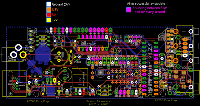
I'm still not having any luck getting this back to an operational state. I've been testing voltages and it seems like all the places on the ATMega chip that I should be getting 3.3V I and getting closer to 1.5. Also, on the BS170 that is next to the J7 (I believe it controls the LCD backlight). On the one pin I have close to 3v the other is ground and the other shows no voltage at all.


Back
Top