LinkMeter v2 Homebrew BBQ Controller - Part 2


Dennis,
Adafruit has pretty good support for their products. If you haven't already, I'd head over their forums and get some help.

dave

Originally posted by Bryan Mayland:
<BLOCKQUOTE class="ip-ubbcode-quote"><div class="ip-ubbcode-quote-title">quote:</div><div class="ip-ubbcode-quote-content">Originally posted by Dennis C:
Tried that several times. still having the same problem :-( Thanks so much for tip not he wires. Didn't realize they were directional.
I'm sorry but I've stared at your boards for 15 minutes now trying to see if I can find something else wrong with them, but they look good with all the parts facing the right direction and everything. I'm really at a loss as to why it wouldn't work. </div></BLOCKQUOTE>
 
Originally posted by Dennis C:
Tried that several times. still having the same problem :-( Thanks so much for tip not he wires. Didn't realize they were directional.

So odd.

This was also my first project last year, and there was a alot of frustration with getting the USBTiny, Atmega and the computer to talk, but don't give up, you'll get it.

If you have a multimeter that has a continuty checker with a buzzer it makes it easy to check connections of the heatermeter.

I too could never get the Atmega programmed on the heatermeter board so bought an Arduino Uno($30 radioshack) and use that to program the chip using the USBTiny to UNO. Then I just put the chip into the Heatermeter.
 
+1
Originally posted by John Bostwick:
I too could never get the Atmega programmed on the heatermeter board so bought an Arduino Uno($30 radioshack) and use that to program the chip using the USBTiny to UNO. Then I just put the chip into the Heatermeter.
 
I too could never get the Atmega programmed on the heatermeter board so bought an Arduino Uno($30 radioshack) and use that to program the chip using the USBTiny to UNO. Then I just put the chip into the Heatermeter.

I'll probably give that a try. I don't want to give up on this project.
 
Originally posted by John Bostwick:
I too could never get the Atmega programmed on the heatermeter board so bought an Arduino Uno($30 radioshack) and use that to program the chip using the USBTiny to UNO. Then I just put the chip into the Heatermeter.

Does the ATmega328p chip attach to the uno directly? Going to pick up the Uno tomorrow to give it a shot.
 
The Uno I got from RS had one in it, so I just flashed it, pulled it and put it in my HM.

I then took the one I bought for my HM and put it in the Uno.

dave

Originally posted by Dennis C:
<BLOCKQUOTE class="ip-ubbcode-quote"><div class="ip-ubbcode-quote-title">quote:</div><div class="ip-ubbcode-quote-content">Originally posted by John Bostwick:
I too could never get the Atmega programmed on the heatermeter board so bought an Arduino Uno($30 radioshack) and use that to program the chip using the USBTiny to UNO. Then I just put the chip into the Heatermeter.

Does the ATmega328p chip attach to the uno directly? Going to pick up the Uno tomorrow to give it a shot. </div></BLOCKQUOTE>
 
I've been reading about this project for the past week and am starting to compile my list of parts. Admittingly, I haven't read all the posts because there are many but I have searched through quite a bit. I was wondering if anyone has tried using probes other than Maverick and if so, is it just a code adjustment that needs to be made or is there a heatermeter board adjustment as well?

Thank you for designing this project. I can't wait for my first smoke with it.
 
Hi Tom,

Yes, you can use other Probes (there have been mentions of Ikea based ones previously).

The main issue when using other probes is knowing the co-efficients which allow the proper termperature to be calculated. There are previous posts on how to do this.

Assuming the probe jack is the same there's no need for adjustment per-se. Board adjustment would only be needed is a different resistor was required to allow the temperature to be read properly (which relates back to the co-efficient point above).

From my experience as a complete newbie... the relative small cost of some maverick probes outweighed the risk / addtional effrot to get others working.

Nick
 
The Uno worked perfect. I'm sure more questions will follow :)

avrdude -c usbtiny -p atmega328P -U flash:w:heatermeter.cpp.hex

avrdude: AVR device initialized and ready to accept instructions

Reading | ################################################## | 100% 0.01s

avrdude: Device signature = 0x1e950f
avrdude: NOTE: FLASH memory has been specified, an erase cycle will be performed
To disable this feature, specify the -D option.
avrdude: erasing chip
avrdude: reading input file "heatermeter.cpp.hex"
avrdude: input file heatermeter.cpp.hex auto detected as Intel Hex
avrdude: writing flash (21948 bytes):

Writing | ################################################## | 100% 35.21s


avrdude: 21948 bytes of flash written
avrdude: verifying flash memory against heatermeter.cpp.hex:
avrdude: load data flash data from input file heatermeter.cpp.hex:
avrdude: input file heatermeter.cpp.hex auto detected as Intel Hex
avrdude: input file heatermeter.cpp.hex contains 21948 bytes
avrdude: reading on-chip flash data:

Reading | ################################################## | 100% 27.06s


avrdude: verifying ...
avrdude: 21948 bytes of flash verified

avrdude: safemode: Fuses OK

avrdude done. Thank you.
 
Feels good when it finally works!

congrats for not giving up,
dave

Originally posted by Dennis C:
The Uno worked perfect. I'm sure more questions will follow :)

avrdude -c usbtiny -p atmega328P -U flash:w:heatermeter.cpp.hex

avrdude: AVR device initialized and ready to accept instructions

Reading | ################################################## | 100% 0.01s

avrdude: Device signature = 0x1e950f
avrdude: NOTE: FLASH memory has been specified, an erase cycle will be performed
To disable this feature, specify the -D option.
avrdude: erasing chip
avrdude: reading input file "heatermeter.cpp.hex"
avrdude: input file heatermeter.cpp.hex auto detected as Intel Hex
avrdude: writing flash (21948 bytes):

Writing | ################################################## | 100% 35.21s


avrdude: 21948 bytes of flash written
avrdude: verifying flash memory against heatermeter.cpp.hex:
avrdude: load data flash data from input file heatermeter.cpp.hex:
avrdude: input file heatermeter.cpp.hex auto detected as Intel Hex
avrdude: input file heatermeter.cpp.hex contains 21948 bytes
avrdude: reading on-chip flash data:

Reading | ################################################## | 100% 27.06s


avrdude: verifying ...
avrdude: 21948 bytes of flash verified

avrdude: safemode: Fuses OK

avrdude done. Thank you.
 
Thanks to everyone's help here of course. The next step is to Flash the WRT and start putting together the wires for the LCD and such.

I might throw the entire router into a project box instead of using the Linksys casing. Not 100% sure on that yet
 
I put my HM in a box, then connect it to the LM via a network cable. That way I can just use the HM without the LM if I want.

I can post a pict if your interested in seeing it.

dave

Originally posted by Dennis C:
Thanks to everyone's help here of course. The next step is to Flash the WRT and start putting together the wires for the LCD and such.

I might throw the entire router into a project box instead of using the Linksys casing. Not 100% sure on that yet
 
Originally posted by D Peart:
I put my HM in a box, then connect it to the LM via a network cable. That way I can just use the HM without the LM if I want.

I can post a pict if your interested in seeing it.

dave

<BLOCKQUOTE class="ip-ubbcode-quote"><div class="ip-ubbcode-quote-title">quote:</div><div class="ip-ubbcode-quote-content">Originally posted by Dennis C:
Thanks to everyone's help here of course. The next step is to Flash the WRT and start putting together the wires for the LCD and such.

I might throw the entire router into a project box instead of using the Linksys casing. Not 100% sure on that yet
</div></BLOCKQUOTE>

That would be great. Thanks

I flashed the WRT54 with the .bin file. Do I have to SSH into the WRT for the TRX or can I do it right from the web interface?
 
Originally posted by D Peart:
I put my HM in a box, then connect it to the LM via a network cable. That way I can just use the HM without the LM if I want.

I can post a pict if your interested in seeing it.

dave

<BLOCKQUOTE class="ip-ubbcode-quote"><div class="ip-ubbcode-quote-title">quote:</div><div class="ip-ubbcode-quote-content">Originally posted by Dennis C:
Thanks to everyone's help here of course. The next step is to Flash the WRT and start putting together the wires for the LCD and such.

I might throw the entire router into a project box instead of using the Linksys casing. Not 100% sure on that yet
</div></BLOCKQUOTE>

I would love to see that. Also, do you still have the LCD template that you mentioned in previous posts?


Click the pic to see a larger version

This is what my old heatermeter looked like. I will probably use the same case with my new updated heatermeter
 
Originally posted by John Bostwick:
This is what my old heatermeter looked like. I will probably use the same case with my new updated heatermeter
That is still the most bad-*** looking Linksys in the universe.

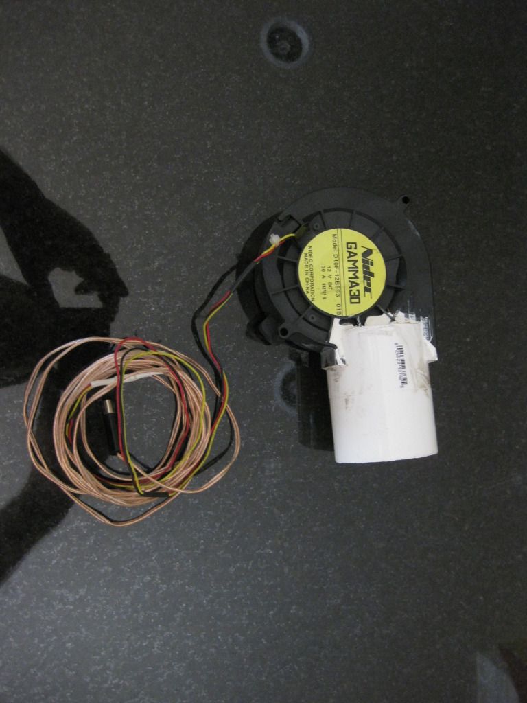
Does everyone remember when I said my cardboard mockup blower mount has bee going strong for years? Well scratch that. Last night I was roasting a whole chicken at 400F and a hot coal bit fell down and leaned against the cardboard "retention plate" which caught fire. The fan fall off and didn't burn but the mount was destroyed. I finished the cook with the fan just wedged in the door.


Guess I need to make time to work on that metal version I had planned.
 
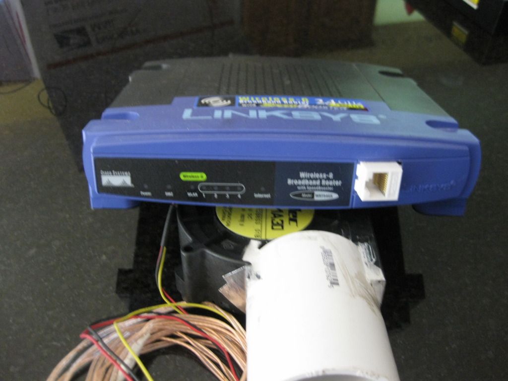
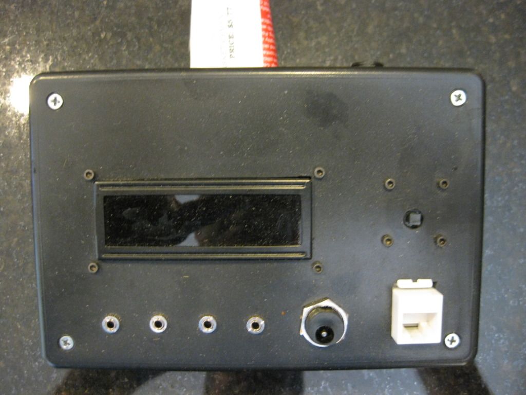
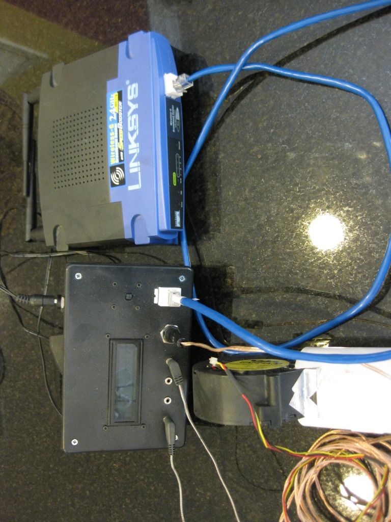
Here are a couple pictures.

This is a 25CFM 12V blower with a 1-1/2" PVC coupler on it to connect to the smoker.
IMG_5256.jpg


This is a female cat-5e jack. It is used to run the 12V power and serial bus from the HM.
IMG_5257.jpg


Enclosure is a 6x4x2 Radio Shack project box. Took a little work to get all the sockets to work, as it is a little thick. Used a countersink bit to get them to fit.
IMG_5260.jpg


The HM connects to the LM with a standard cat5 cable.
IMG_5261.jpg


dave
 
Tim,
I put it in my public Wuala folder. You should be able to get it here:

https://www.wuala.com/dpeart/P...ic/?key=2TDJUHmFY9hs


dave

Originally posted by Tom Kole:
<BLOCKQUOTE class="ip-ubbcode-quote"><div class="ip-ubbcode-quote-title">quote:</div><div class="ip-ubbcode-quote-content">Originally posted by D Peart:
I put my HM in a box, then connect it to the LM via a network cable. That way I can just use the HM without the LM if I want.

I can post a pict if your interested in seeing it.

dave

<BLOCKQUOTE class="ip-ubbcode-quote"><div class="ip-ubbcode-quote-title">quote:</div><div class="ip-ubbcode-quote-content">Originally posted by Dennis C:
Thanks to everyone's help here of course. The next step is to Flash the WRT and start putting together the wires for the LCD and such.

I might throw the entire router into a project box instead of using the Linksys casing. Not 100% sure on that yet
</div></BLOCKQUOTE>

I would love to see that. Also, do you still have the LCD template that you mentioned in previous posts? </div></BLOCKQUOTE>
 
OK Guys, this project is really making me feel stupid.I need to reach out to you for help once again. My current status is that I have successfully burned the boot loader onto the AtMega328P. I am ready to install the heatmeter code onto the chip and I downloaded the latest version from the GitHub hosting site. I extracted the "Arduino" files into a folder on my hard disk in the same folder as the "examples" below the "arduino-1.0.1" folder (off the root of the hard drive). I open the "heatmeter.ino" file in the development environment and try to compile it and I get a number of errors that indicate that required files are missing (I believe that they are the files in the Library's sub folder). Obviously as a Newoob, I am failing to complete some required step.

Would anyone mind telling me what I should be doing? (Other then buying a "Stoker") ;-)
 
Originally posted by Kevin Scott:
OK Guys, this project is really making me feel stupid.I need to reach out to you for help once again. My current status is that I have successfully burned the boot loader onto the AtMega328P. I am ready to install the heatmeter code onto the chip and I downloaded the latest version from the GitHub hosting site. I extracted the "Arduino" files into a folder on my hard disk in the same folder as the "examples" below the "arduino-1.0.1" folder (off the root of the hard drive). I open the "heatmeter.ino" file in the development environment and try to compile it and I get a number of errors that indicate that required files are missing (I believe that they are the files in the Library's sub folder). Obviously as a Newoob, I am failing to complete some required step.

Would anyone mind telling me what I should be doing? (Other then buying a "Stoker") ;-)

put the library files(jeelib,ShiftRegLCD) into the library folder in the arduino-1.0.1.


Back
Top