HeaterMeter + LinkSys WiFi Router = LinkMeter


Ed or brian, I was wondering if you could give me a hand.

I am looking for replacement parts in the NTE http://www.nteinc.com/ list of parts as I have a local supplier for them.

What would be a good replacement for the irl-510 and the Mcp1702-33. I can't seem to find them on there site.
 
Oh now that is awesome looking, Ed. Was this with the toner-transfer method?

I also got my copper blanks in today and some etch resist ink. Got a bottle of hydrochloric acid and I'm ready to wreck some copper this weekend! Also I just pushed new HeaterMeter and LinkMeter code to github. Working "RF Manager"! Still a little cleanup but at least it tracks packet loss and seen probes. Then I add the ability to map RemoteDevice+Port to a HeaterMeter "probe" index, and we're golden.

For those who may be confused by the monikers, I use HeaterMeter to describe code that runs on the Arduino / AVR / ATMega and LinkMeter to describe the code that runs on the router.

As a heads up, Ed... we may be able to drop the resistor on the SOFTRESET pin. I want to do some more testing to see if that is actually better than with the resistor first though. Also, we might want to swap SOFTRESET and the WIRELESS_LED because the reset is on a PWM pin and we might be able to do something more fun with PWMing the LED and the reset is just an on/off. My code is still following our current design, but we should consider both these before finalizing.

Golly, I keep looking at that picture of the circuit board you made. It is so pretty!
 
icon_cool.gif
I like the board Ed, Looks really good.

I too was using the Radioshack stuff but that stuff stinks to like nothing else.
 
Originally posted by Ed Pinnell:
Interesting suggestion. I think I'd be inclined to keep the reset button/10k resistor outline on the board just in case...dare I say it...the nSOFTRESET didn't work for some reason. Do you see that as a problem if it were populated for some reason? Is that nRESET function programmed in with the bootloader [and would you do away with it if is?] or is it a hardware function?
Oh yeah, the 10k pullup needs to stay to keep the nRESET line high, and even the nSOFTRESET relies on the 10k being there to limit the current while pulling the line low.

I'm also a proponent of the physical button as well, for two reasons. The first being that it is required for the initial flash that you manually reset the AVR. The second, is like you say, something can go wrong with the soft reset. It has been working perfectly in my setup, but if you flash code that "locks up" the AVR, you can lose the soft reset ability and have to fix it manually.

The soft reset is a function of the HeaterMeter code and is something that is not recommended by ATmel. Their recommendation is to use the watchdog to reset it, but because the standard Optiboot bootloader (the 'Uno' bootloader) won't let you flash unless the reboot reason was that the nRESET was pulled low that won't work. Like I've said, my solution has been working perfectly on both a 5V and a 3.3V system here so even though it might be not recommended, it seems to work well enough for our purposes.

Good point regarding the HCl and baking soda. I've got gloves and goggles but you're right about having some base nearby. Also love that silkscreen! You are really making some professional-looking product there, I hope my software can keep up!
 
After further testing, the 1k resistor should probably stay. Yeah I meant the one in series with the 1N5817 connected to nSOFTRESET. I thought the lack of resistance would help bring the line lower when I triggered it, aaaand it sort of does but it makes a slight quick rebound lowering the overall amount of time the line is held low. Just leave it because there's no use trying to improve on it because it works!

When you say you are thinking of swapping the WIRELESS_LED pin with the nRESET pin
To clarify, I meant swapping the WIRELESS_LED and nSOFTRESET pins. Meaning Digital Pin 7 (physical pin 13) -> 1k Resistor -> 1N5817 (reversed) -> nRESET/capacitor and Digital Pin 9 (physical pin 15) -> LED/Resistor.
 
Haha nope that's all I got! I'm sorry about the change. I sort of arbitrarily picked the pins for the reset and the LED but when I was working with it this week I slapped myself for not realizing only one of them was a PWM and it wasn't the LED.

In other news, my LinkMeter is currently receiving data from the wireless node. Do we have a catchy name for these yet? LinkMeter Wireless Probe Node is just too darn long to refer to.

In my setup I removed the thermistor and ran a wire to the battery so I could watch how long it takes to kill a single AA that is hooked up to a boost converter powering the whole remote unit. I have the Arduino power down and sample the ADC every 8 seconds and only transmit if the value has changed, or if 64 seconds has passed since the last transmit. 2 hours later and the AA battery (which is a RadioShack AA circa 1999) is still hanging around the same value. My design supports up to 4 probes per remote sensor, and up to 4 remote sensors all mapping back onto the standard 4 HeaterMeter probes.
 
At the risk of slightly derailing the thread, can you share some of your Eagle board DRC settings? Specifically, your clearance and your minimum trace width and any other sizes you have found to be ideal for home etching. I had seen that for making PCBs that a 12mil trace with an 8mil spacing was really safe but I printed one out at that size and thought "Yeah that's going to get eaten clean off the board". 25mill looks more reasonable.

Also what size drill bits should I get for making vias? I don't want to buy a "50 piece set" that includes like 3 of the right size I need and 47 way too big or small bits. Man this inkjet printing thing is hard. The first 5 tries I couldn't even get the printer to print in the designated PCB area! Stupid margins.
 
I finally got around to making my button board for the LinkMeter. I had been putting if off because I wanted to use a single 4-way tactile switch instead of 4 individual buttons and the switch I had selected had a strange pin spacing so it wouldn't go on standard 0.1" breadboard.

I used this 80 cent switch (datasheet) and a square cap. I wasn't sure what to build it on so I did what anyone else would. Wander around the house looking for something that could hold a button. Oh what's this? An AOL cd?!

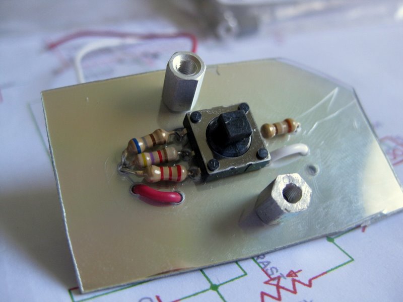
I used an awl to punch dimples in the CD where the pins would go and used a 1/16" drill bit to make the holes
linkmeter-2011052901.JPG


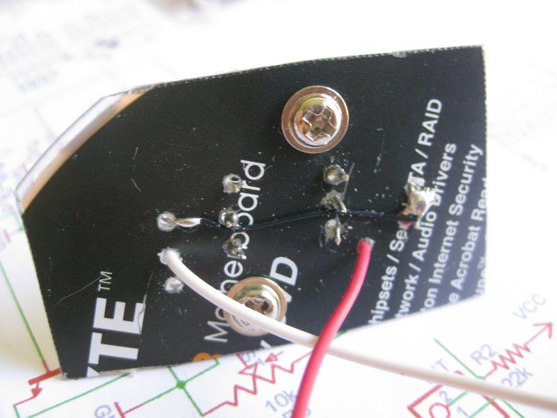
Wiring it is extremely easy due to there only being a switch. I just made one hole and stuck 3 resistors though it, connected to VCC then one hole on the other side for the other resistor and brought the power across. 2 wires to bring VCC and the signal back. BAM done and soldered in like 10 minutes. Extremely easy.
linkmeter-2011052902.JPG

linkmeter-2011052903.JPG


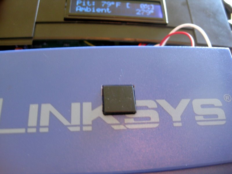
I used a step drill bit to make a hole the size of the button, then used a file to square the hole to the exact size of the button. Put some hot glue on the standoffs and stuck it to the linksys panel.
linkmeter-2011052904.JPG


Once the glue was dry, I unscrewed the button board from the standoffs and then widened the hole with the file again so it had room to rock. I didn't do this before I put the button in because otherwise it would make the button hard to center in the cutout while waiting for the glue to set.

I really like this button and having a 4 way switch feels a lot more natural than using the 4 individual buttons to navigate. Even better, it costs less than the 4x tactile buttons from SparkFun.
 
Oh man thanks for all that information. I'll be sure to check the trace widths, both printed and etched to see how they fare compared to in EAGLE. Can you tell the autorouter to sure different trace widths for different classes of nets, or did you run all the traces all manually?

Good news! I just pushed a bunch of new crap up to github. This allows you to set LinkMeter Wireless Remote Node associations with HeaterMeter probes via URL (no web pager for it). The "home" web page now also shows the wireless state if a probe is associated with an RF source. The signal meter isn't that great yet but at least you can get an idea if you're losing packets. Green for perfect, yellow for 80%, red for below 80% and blank black for "You're crazy, I haven't seen this probe at all recently".

Eventually this will all get a nice web interface to control, but for now the information is in the README.txt
 
Haha I see America and Waldo! I think you still have a little bit of space in the corner there. Can I suggest you somehow work in a high pressure laser so the LinkMeter can also be used to light the grill? I kid, I kid. It looks great!
 
That's awesome! I've just spent all day working on the inkjet method. Took me until about 2pm to print reliably on paper with regular ink in a way that even two-sided designs looked doable. Oddly enough, printing from Photoshop Elements was a lot less precise than from regular MS Paint.

Unwrapped the special inkjet cartridge with special resist ink aaaand it doesn't fit my printer. I tried printing with normal ink anyway with two coats and heating the board in between, hoping it was pigment based but it came off the instant it hit the etchant.

I *can* print some really nice looking two-sided mockup boards with silkscreen and all though!
 
I actually bought special etch resist ink but the problem was it only came prefilled in one cartridge. The list of supported printers had a R300 and I thought it might have meant R300-series but I guess not. I went and picked up an empty cartridge that does fit my printer and I'll use a syringe to transfer the ink over.

I've been playing around with remote nodes and seeing how long a battery lasts on them but after about a week of running and the battery not dieing, I got bored. I saw these Solar LED path lights at Lowe's (because I am always there) and noticed they ran on a single AA battery. A solar panel, LED, boost converter, rechargable battery, battery holder, and an enclosure for under $5? Sold! Unfortunately the boost converter inside only boosts to 2.7V but the solar panel and schottkey diode work and pump out about 40mA in afternoon sunlight. Sitting in direct sun the battery gains more power in an hour than it uses all day. This will probably kill the poor NiCad battery though because it has the memory effect and this is originally designed to kill the battery every day.
7txYV.jpg


It is too bad it only outputs 2.7V and I can't find a part replacement that would convert it to 3.3V, otherwise this would be a pretty sweet way to get a cheap AA power supply to run a remote node.
 
But hey who cares about that when there's BBQ going on.

I drilled a couple holes in the feet of the router and stuck a bungee cord in there which makes it so I can see the LCD from inside and the controller takes no space on the currently non-existent table!
 
Originally posted by John Bostwick:
Looks really Awsome. I do have a question.

What is the part number of what looks like a female header on the IRl510? having a hard time finding it on Digikey

Edit: I think I found it http://search.digikey.com/scri...Detail&name=S7001-ND
I too looked at that and thought "I have not seen one of those before" but I guess I have, seeing that part. My favorite part is the resistor parade going on down by the probe connector.
 
icon_biggrin.gif
im a proud owner of a Heatermeter, I finally was able to get it working. Still have some work. and if and when i get everything fab. i could still add the wireless, which i have but, i wanted to make sure everything else works before i start screwing around with wireless. Thank to goes to Ed and Bryan for Answering my Questions, Thank-you

lcdpic.jpg
 
John, congrats! I would love to know what you had to do to solve the LCD issues you were having. That is the same point where I left off on mine.


Back
Top