HeaterMeter + LinkSys WiFi Router = LinkMeter


The reason I didn't go with the 12V -> TO92 5V linear -> TO92 3V linear was because I was concerned with the 7V drop at the 5V stage pulling say 100mA would be eating at least 0.7W and I didn't think a TO92 would handle that.

Funny you should mention the 10.5V drop, because actually I realized last night I had my WRT54GL plugged in to a 9V power supply instead of a 12V. It was working fine, so there's a datapoint for you.
 
== Config Change ==
You'll probably need to reset your config following the push I just did ending in commit f7d82da84104c23d6cca.

The probe configuration structures have been completely reorganized such that each probe has its own steinhart coefficients and resistor values. The new default is to assume every probe is a Maverick, is biased with a 10k ohm resistor, and is named "Probe".

Once your configuration is reset, you'll probably want to update your config to match your device. Open the serial monitor, set the line ending to anything besides "No line ending". Enter your probe coefficients:
/set?pc#=A,B,C,Rknown
# = the probe number, 0-pit 1-food1, 2-food2, 3-ambient
A,B,C = The steinhart coefficients
Rknown = The value of the fixed side of your probe voltage divider.

If you want to get back to the old defaults with 22k ohm resistors:
/set?pc0=2.3067434e-4,2.3696596e-4,1.2636414e-7,2.2e+4
/set?pc1=2.3067434e-4,2.3696596e-4,1.2636414e-7,2.2e+4
/set?pc2=2.3067434e-4,2.3696596e-4,1.2636414e-7,2.2e+4
/set?pc3=8.98053228e-4,2.49263324e-4,2.04047542e-7,2.2e+4

And set the probnames with the old /set?pn#=XXX method:
/set?pn0=Pit
/set?pn1=Food Probe1
/set?pn2=Food Probe2
/set?pn3=Ambient
 
Ah crap, I just realized that when I went to add the LCD backlight configuration that if I add more things to the config it will mess up the probes every time. Dahmit! Gonna have to come up with a better solution for that.
 
Originally posted by Ed Pinnell:
Ah, you forgot the to add in the ~1.7v dropout voltage, so it's more like a 5v (12 - 5v - 1.7v DOV) drop multiplied by the actual current draw, which you said
What I had seen in a Texas Instruments guide to linear regulator thermal management, the power was calculated as (Vi - Vout) * Iout (neglecting quiescent current).

Anyway, I do see your point of having everything self-contained. I was just trying to keep the part count down. For me, 1 more part seems to add 5 more routing headaches.
 
The building continues. I printed out the LCD datasheet at 84.2% size (so the measurements were actual size) and used it as a template. Then I used my dremel with a cutoff wheel to make the hole and finally make the exact fit with a triangular file. I've got some standoffs I hope to cut to size then glue to the inside of the case to hold the whole thing in place.
linkmeter-2011050701.JPG

linkmeter-2011050702.JPG


I think it came out alright, although I did have to position the LCD back some from where Ed had his because my LCD pin header, being vertical, got in the way.
 
I went to Mouser today to buy some standoffs and I figured I'd buy some different buttons just to see if there are any better than the SparkFun buttons. I picked up some standard 12mm tactile buttons with caps but then right before I was going to checkout, I thought of this:
4 way switch datasheet

That with a square cap is the same price as 2 SparkFun buttons and takes a lot less space. Sure it looks like it is going to be a pain to mount as the pin spacing is 10.3mm by 6.5mm but I figure that's something you can just drill out of a square of material.
 
And another thing! (what else do I have to do besides sit around and drink beer and watch the web site?)
linkmeter-2011050703.png


I imagine at some point this will feed off the high alarm point, but for now here's a beef clod headed into plateau and some fixed destinations.
 
Originally posted by Ed Pinnell:
If you want to eliminate that annoying gap in the bezel that the light from the backlight spills out of, you can cut a strip of black electrical tape
Ah! How did you know I was looking for a way to do that?

After I cut the hole, I was kicking myself for not just cutting a hole big enough for the actual display portion of the LCD and cutting a piece of clear lexan that would fit in the hole and mounting the LCD behind it. Ahhh maybe next build.
 
Oh see it is made that way because you see, light comes out of the other side so the engineer decided that they'd let light come out the "closed" side too! And I know about injuring myself, I Dremeled my finger *three* times this morning.

How about some more construction photos?
linkmeter-2011050704.JPG

Wiring up the 2.5mm probe jacks. Note there's a black wire missing here because obviously you need to actually connect the ground wire, not just link the three. Ed may try to tell you that you have to ground the third pin too, but I don't think he knows the secret: that I've fixed this in software now so it is ok to just have the probe wire and ground. This assumes your probe wire (orange here) is connected to the analog line and 10k resistor junction.

linkmeter-2011050705.JPG

Installed in the router. You can see the extra black wire added here coming out the left.

linkmeter-2011050706.JPG

The view from the outside. Ed, is there a secret easy tip to erase sloppy pliers marks?

linkmeter-2011050707.JPG

And I am completely shocked, all the probes work as well as the fan on the first try. Of course, as I was putting it together, I snagged one of the wires and broke the wire to the LCD. Easy enough to fix though. Still no buttons but I'll get to that later.
 
Haha, somebody gonna get sued!

Update on what is going on with development
My hardware build is done for now. It has what I think are a couple major flaws but that doesn't really matter at this point, I can fix it later. Don't do what I do! I've got something that spits out data though, so that's close enough to continue development.

Software-wise, my focus right now is converting the shell scripting I use to pump data into the rrd into LUA. I love OpenWRT. There, I said it. The LUA subsystem with the nixio module means I can create pipes and redirect things right into and out of the script. What we'll have is a daemon running that reads and writes from the serial port, has a pipe open to rrdtool to feed it data, and creates unix sockets to allow you to still interact with HeaterMeter as if you're connected directly. It is really the best way I was hoping to do it, and it is actually pretty straightforward. What I'll end up with is an ipkg that can be installed with all the requisite parts.

After that I'll work on integration of the RFM12B remote probes. I'm sure the previous step will keep me busy all week though.
 
john: this is only my opinion:
Ed/Byron feel free to jump in /correct me.
there are at least 3-1/2 methods of going from schematic to permanent circuit card.
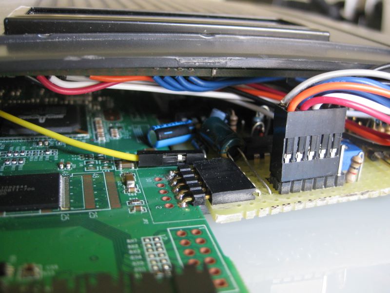
1) point to point wiring-> this is the most common of what you see here.
advantages: easy to see and follow from schematic to board
cheap. compact, can handle complicated circuits
disadvantages: underside Spaghetti
hard to troubleshoot.
hard to see if solder is good or not.
2) custom etched boards.
a) professionally done
Dis: Expensive, especially in low quantities
hard to change if you make a mistake.
adv: can be single or multi-layered compact
can handle surface mount or weird.spacing
b) make your own:
adv: cheaper than professional
dis: got to drill all the holes,
harsh chemicals.
not so easy to do correctly.
3) stripboard/veroboard (my choice)
adv : cheap
high quality end result.
easy to do.
dis: not so compact.
not supported well with modern tools (eagle ect.)
more work up front in the layout
3.5) 3 pad pattern stripboard.
see http://en.wikipedia.org/wiki/Stripboard (tripad)

build you own arduino/stripboard clone
see http://txapuzas.blogspot.com/2...ino-stripboard.html# its in spanish but there is a translation page. just hit the British flag
BTW i am sending a bit of vector 8022 circboard to Ed. he can make anything work.
I have the shift reg layout file somewhere that I can share if there is any interest.
 
Huzzah! I finally gave up on trying to do it the right way and figured I'll just do it my own bloiting way. Another 4 hours on it this morning and yay I've got a working patched avrdude package, which I built into my firmware image and flashed the router, promptly bricking it.

There is only like a 1 second bootwait before router would boot and crash so it took about an hour to figure out that it was doing that and was able to recover it with a stock image. Square one is a good place to be sometimes.

Then I tackled the problem of making the linkmeter package. Done! A few fixes and we have a working linkmeter! There's still plenty to do. You've got to manually start the daemon, but I'm rewriting the daemon so there's no point in fixing that just yet.
 
Originally posted by Ed Pinnell:
I'm curious over here...were you monitoring the serial console port while it booted, and if so did it give you any indication that it crashed?
Nope! I somehow have managed to damage my 3.3V TTL serial cable so that it only transmits now for some reason, the receive line is kaput. Even if I take the Rx and Tx wires on it and twist them together, I don't get my keys echoed back in putty. That cost me about 10 minutes of scratching my head as to why the router wasn't even sending data out the serial port.

What was causing it was that I removed libc from my OpenWRT build by mistake. Kiiiiinda important.
 
firstmd.jpg


I hate wires, lol. I think my first pcb came out fairly good. I was very pleased at how easy it was, using a inkjet printer. But after doing some test drills i believe now thats going to be a pain. as i was test drilling the pcd and the dremel just has to much play in it so will take a safe route and take it to work and drill it out on a drill press in our tooling department(nice when you work a 3rd shift and they are not around to get in your way, lol)

After the drilling i will still have about 30 wires to solder in.
 
Wow that looks great! That inkjet method is pretty sweet. At some point I am going to try it once I have some free time.

Ed, I've just pushed up some web changes to git, one I think you'll be especially interested in: moving the graph into the blue and centering it. I remember you had some comments about the line colors but I can't seem to find what you said in any of my saved emails. I know you had a focus group give their opinions.

I've already decreased the brightness of the ambient probe so it blends in more, and gotten rid of the legend. What else did you say?
Image

I've also started using tags on my git commit messages to indicate what subsystem it is from.
[www] Web pages
[hm] HeaterMeter avr/arduino code and support
[lm] LinkMeter code
[openwrt] OpenWRT packages and configuration
 
John, can you tell us a little more about your printing setup? Like what kind of printer you used and which resist ink? When I get the time, I'd like to start doing my own boards too.

Updates:
I've pushed an rrdtool build package up to github with a LUA binding for it. This way we don't have to spawn a new rrdupdate process every 2 seconds, nor do I have to keep the process running with a pipe between the linkmeter daemon it. I'm sort of not pleased because the rrdtool configure script runs lua on the host PC to determine the version number, because it is cross compiling it gets the host lua version instead of the target lua version, which could cause a headache down the road. If anyone else wants to take a crack at doing it in a more robust manner, I'm all ears.

Next on the list is a proper uci configuration and init.d scripts so the daemon will be launched properly and get a default configuration when installed. I think once that's working I'll hop over to wireless probes.
 
Ouch. That is a lot of work right there. It almost makes me not want to mention that I was going to ask you to add a LED+resistor on Digital 7 for a RFM12B receive indicator light. (ducks)

Also I should have asked about this before, but why does the serial port voltage divider use 18k/12k resistors to level shift, and the SPI bus use 10k/4.7k?
 
Yeah the router is still optional, although you'll need a serial connection to so the initial probe config. I will probably change this to just work by default, once I have time.

I've poked a hole in my firewall to get to the LinkMeter (which is just sitting on the table here) for a work-in-progress Live Demo:
http://home.capnbry.net:22676/

The ambient temperature is actually the current LUA memory use. I'm having a bit of a memory leak problem I'm trying to narrow down.
 
Are you joking with me? You can set the setpoint all you want if you meant that you didn't want to mess anything up.

Good news! I found the memory leak in the RRD LUA bindings. Thank goodness it was in the bindings and not in LUA or RRD itself. That would have been a nightmare to try to track down but luckily it was just some extra strings in the wrapper. It took me longer to get rrdtool to build on my system than it did to find it!

I had tried to view the graph this morning and it took about a minute to load, and sshing in took a couple minutes before I got to a shell. Funny how a 20 byte string that you don't free every 2 seconds can take down the whole system.
 
Originally posted by Ed Pinnell:
It kinda takes the funny out of it when I gotta explain the joke, tho'. You programmers sure are a serious bunch of folks...but talk about memory leaks? The other day we were on our way out to dinner and my wife noticed she put her pants on inside out! I told her I hoped that was the clean side...
Haha! Oh Ed, you crack me up. Of course I'm serious-- if someone says something doesn't work, I gotta fix it!


Back
Top