Blue Sky Stepper Damper thread - Breakout from RaspberryPi + LinkMeter blue sky


Well the Atmel does not source enough current to power the servo directly from an output pin. It seems that it just cannot respond with the peak current needed to change the servo. I did hook it up via a PNP transistor (only have PNP on hand) but did get it to work when driving the output low and to stop working when driving the output high. So that part works :)

dave

Somebody did share with me about using a cap to provide a "kick" to move a servo or solenoid, then a resister to limit current flow to "hold" position. Possibly exposing my ignorance here but can you charge the cap with the output pin, and get enough "kick" to move the servo, then use the output pin current to hold the servo if so desired ??

Bill
 
That could work. I'll give it a try.

dave

Somebody did share with me about using a cap to provide a "kick" to move a servo or solenoid, then a resister to limit current flow to "hold" position. Possibly exposing my ignorance here but can you charge the cap with the output pin, and get enough "kick" to move the servo, then use the output pin current to hold the servo if so desired ??

Bill
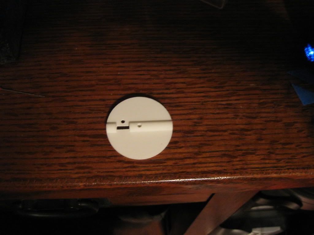
 
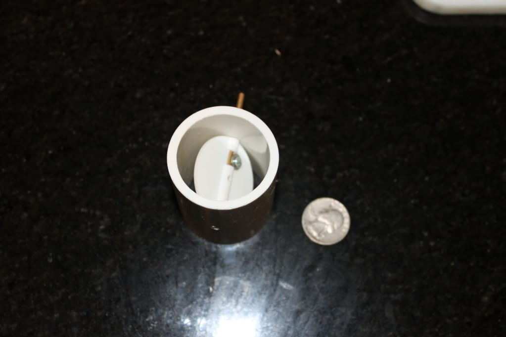
Got my valve from Shapeways today. This is pretty cool, it looks just like the drawing above. I test fit it in a couple pieces of 1.5" pvc and in one it fits nicely and in a second it is just a smidge too large. So it seems to match what I expected. Now to create the housing for it and get a servo hooked up to it.

IMG_5506.jpg
 
Last edited:
Bryan,

I have two of the valves put together, just need to add the servo. Plan to do that this week.

Could you make it so that the requested fan speed is sent to the lmremote and then on the lmremote I can use map() to scale it from 0-100 -> 0-90 degrees for the servo and write it out a digital pin? Nothing fancy, just something for me to start playing with. Pick any of the pins as I'll just be using it on my proto board and Uno. If so that would be awesome.

I'm wondering if the delayed response of not using a fan is going mess up the PID algorithm. May need to tweak it to get it to work best. So I'd like to play with it a little.

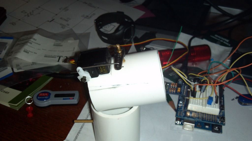
Here is a pict of what I have now:
IMG_3755.jpg


thanks,
dave
 
Last edited:
It's a pretty big change but I might be able to get something usable to you before I head out for Thanksgiving. If it doesn't work, you're going to be SOL until next week though.

You're not running this on batteries yet are you? Because I'll have to disable powersaving to get this working at first.
 
No batteries. This is just for me to test with. I'm not going to cook with it, just see if I can get something put together. If I get that working I may do an empty cooker run (cook a pan of water).

dave

It's a pretty big change but I might be able to get something usable to you before I head out for Thanksgiving. If it doesn't work, you're going to be SOL until next week though.

You're not running this on batteries yet are you? Because I'll have to disable powersaving to get this working at first.
 
Last edited:
Alright, Dave. I've pushed up source code that makes the HeaterMeter base station transmit the fan speed once a second for now. The lmremote code is also updated. Look for the packetReceived function, there's a comment where you can add your servo code.
 
That was fast!

I got the code, compiled and running on the HM and lmremote. I see the val of the fan speed coming in on the packet. I'll work on getting the servo running and let you know how it goes.

thanks so much!
dave

Alright, Dave. I've pushed up source code that makes the HeaterMeter base station transmit the fan speed once a second for now. The lmremote code is also updated. Look for the packetReceived function, there's a comment where you can add your servo code.
 
Woohoo! It works! Now to get the servo hooked up to the valve and put it all together.

Pretty cool, I can go to the manual fan speed and watch it move, I can hit open lid mode with the button and watch it go to zero, then come out or open lid mode and have it go right back. AND it works via setting it in the web interface!

I know this to be expected, but it is . . . ALIVE!

dave
 
Yayyyyyyyy! Sometimes when things work, even the programmers who write it are surprised. Glad it works and we didn't have to spend 8 hours scratching our heads. The updates in the final version will be less frequent, maybe once every 4-5 seconds based on my guestimation, but I'll have to do some measurements to know for sure. I'll eventually try to get the lmremote to "sync up" with the fan updates so it does a measurement and tries to receive the fan info at the same time, and sleeps the rest of the time.

That should give you something to play with though and see if it gives enough control to make a fanless HeaterMeter a reality. Happy Thanksgiving, Dave!
 
I'm trying to use one of the probes to read a pot so that I can adjust the trim offset for the servo. I'd like to use a probe because you have already gone through the trouble of stabilizing the ADC and such.

I set _enableProbePins = 0x02, but should it be 0x03? Not sure if it is a mask or not.

Then in checkTemps I'd capture the value and use that for my trim offset.

Its not working so I thought I'd ask, but will continue looking into it.

dave
 
Yes the _enableProbePins is a bitfield so 1 = Analog 0, 2 = Analog 1, 4 = Analog 2, etc. Setting it to 0x02 would just read Analog 1, so if you want to read both A0 and A1 it needs to be 0x03.
 
Thanks, for now I've just set the trim offset to 12 in the code. I've shown that I can get the ADC to read the pot, but I get inconsistent results. I'll change the mask to 0x03 and use the enableADC and stabilizeADC functions to
see if I can get stable results.

I have also been able to take the suggestion of a "starter" cap, and used 100uF cap to be able to power the servo from a digital IO pin. The final size may be a little larger, just need to play with it a little more to see if it works at 3.3v.

I have also gotten the valve setup with the appropriate sized horn. Turns out there is an excel spreadsheet that does all the calculations for you. I hope to be able to get my first fanless test run done this week. Suggestions on how to get the PID parameters for this new fanless mode? Should I try the auto tune? I thought I read somewhere that this did not work well for you. My concern is that with the fanless mode the response time will be significantly different that with the fan stoking the fire.

dave
 
Last edited:
For your trim pot, I'm not sure how you have it hooked up or how you're reading it, but you'd want to insert your code somewhere after stabilizeADC() and before newTempsAvailable(). The transmit disables the ADC unit because it pulls a lot of power that isn't needed during transmit.

What does the "starter" cap do? If you've just got it on the digital line going between the avr and the servo power, it isn't doing anything useful for supplying current. A MOSFET would be your best bet for being an on/off power switch.

For figuring out PID parameters, there's no autotune I've found that is worth a damn. Try the "Manual Tuning" section from https://github.com/CapnBry/HeaterMeter/wiki/PID-Tuning]the wiki. Basically set your B, I and D terms to 0 and play with P until you get a stable oscillation around the setpoint.
 
The starter cap is from the digital out (set to HIGH right now) and ground, in parallel to the servo. It basically store charge to supply the servo the starting current needed to get it moving. I think it is doing something because without it the servo won't move and with it, the servo moved. Now when we start enabling/disabling the digital outputs, there would be some "charge" time for the cap to charge before it would provide any benefit. I'm hoping that the charge time will be fast enough to provide benefit. I also see differences in the servo move time when using different sized capacitors.

If not, a simple N-FET works as well, as I verified that too.

dave
 
Ah gotcha. I suppose you charge it up before requesting the servo move and it provides the extra oomph. I'm not sure if you've done any measurements, but I', also wondering if the current to charge the capacitor is above the spec of the AVR. Does the impedance of the servo power lines limit the current in any way? I'd be concerned that the AVR is supplying like 100mA or something when it turns on to charge the cap.
 
Good question. I don't know the internal impedance for the AVR. In the end a N-FET may be just as easy, and take the same room on the board. It would definitely be a more robust solution.

dave
 
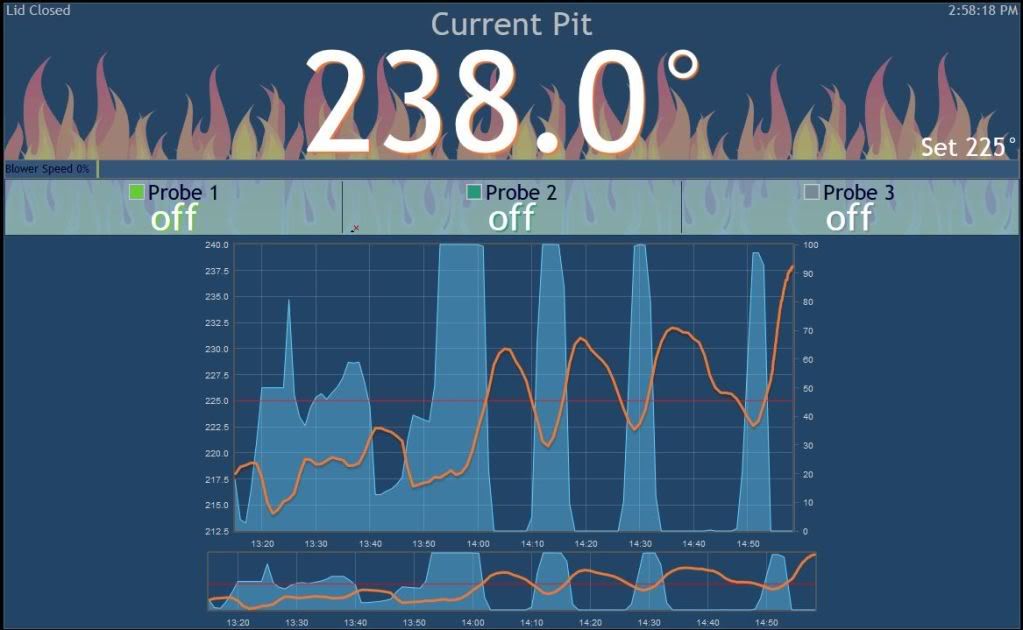
PID tuner I am not! The good news is that it can control the temperature, the bad news is that I don't know how to tune it.

PIDTuning.jpg


dave
 
One issue I'm having is that the whole thing keeps hanging. I don't realize it until after the temp is wacked and I have to reset the rPi. Not sure why it is so unstable. Makes it difficult to tune, but I think I'm getting closer.

dave


Back
Top