Blue Sky Stepper Damper thread - Breakout from RaspberryPi + LinkMeter blue sky


I've contacted the Geek with Fire to see how his concept is working.
just to follow up, I heard back from him. He got busy with other things and had to leave the tinkering on that behind. He now uses a BBQGuru, which he says isn't as steady accurate as his method, but is good enough. I find that pretty encouraging.

I'm tempted to fool around with a throttle body valve and a Hall-effect TPS but given how well Geek with Fire's system worked, I think I might start there.
 
I have been playing around with the idea of using 1/4" throw 5v solenoids to open and close a rectangular damper, the surface area of one say 6" wide and 2" high (do not remember the exact numbers) came out close to a 1.5" round pipe, and you could put a slide valve on the face of it to allow you to trim your "idle" heat.

I have the solenoids from sparkfun....just need to work out how to reduce 12 volt output from my Auber to 5 volt and do the mechanical work to rig it up for a try.
https://www.sparkfun.com/products/11015

Probably better make my own topic for this :)


Bill

Not sure how much you wanted to spend. This is the way some industrial controls work. Basically a valve like this that takes a 4-20 milliamp signal:

http://www.ebay.com/itm/Belimo-B230...498?pt=LH_DefaultDomain_0&hash=item1c2c4e1af2

and then a PID controller like this to control the valve and monitor the pit temperature:

http://www.ebay.com/itm/PID-Digital...669?pt=LH_DefaultDomain_0&hash=item20cb8a18ed

Mount the PID controller in some sort of "box" and for close to $70 you should have a decent setup. Of course it's missing a few bells and whistles like wireless and food temperature monitoring, but it will work. If the valve is too small you could rig it up to some sort of damper, but I would think an 1 1/2" valve would be sufficient size.

Edit: There's also a 1" valve listed. Guess it depends on what you have for a smoker.

http://www.ebay.com/itm/Belimo-B223...835?pt=LH_DefaultDomain_0&hash=item1c2c4e33b3
 
Last edited:
Here is what I have so far:
Capture-1.jpg


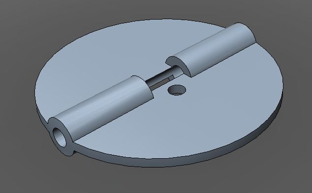
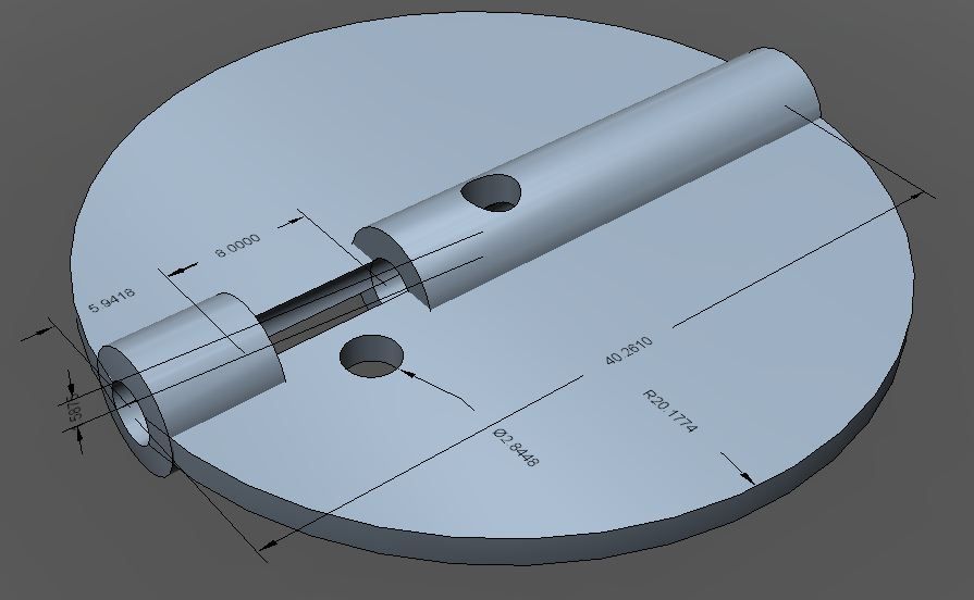
It is sized to fit inside a 1.5 inch PVC pipe. There is .5mm clearance all the way around, so essentially it is 1mm smaller in diameter than the inside diameter for the pipe. I still need to fillet the edges because it will not rotate in the pipe as is.

The small hole is to fit a 4-40 machine screw with 5/16" flat washer on the top and bottom. This washer will overlap the 1/8" rod down the center exactly at is center, allowing you to clamp the rod into the valve.

To get one made from Ponoko is:
Durable Gloss Plastic - Black
Size: 39.4 x 39.8 x 8.6 mm
Volume: 2.47 cm³
Making: $4.18
Material: $0.76
Total: $4.94

comments? suggestions?
dave
 
I created a new one. I placed a hole centered in the valve that will fit a 4-40 machine screw. I also created the size of the valve to be 1.59" in diameter with is the minimum internal diameter of a 1.5" PVC pipe. Previously I had reduced the diameter by 1mm for clearance. My concerns is that too much clearance and you don't stop the flow of air. With this solution, you can place the screw in the center hole, put it in a drill press/lathe and using a file or something reduce the diameter to fit your piece of pipe exactly.

valve3.jpg
 
One step forward, 4 days back. Shapeway got hit by Sandy so they expect to be out of service for four days due to power loss at their ISP. I guess that means I get four more days to modify and tweak.

dave
 
Wow that's a bit of a setback for them, considering how much I'd heard they recently invested into new equipment there. Hope only their power was damaged and not their manufacturing. That said, this design actually looks simple enough to build at home. I have a 42mm hole saw, some hardboard, and some small tubing, I wonder if something similar can be fashioned out of that and a little JB Weld.

What are the holes for, both the gap in the pipe and the two drills? I'm trying to envision how you're going to have it hooked up.
 
The hole with the gap is for a 4-40 machine screw with a 5/16" washer. The washer will overlay the 1/8" brass rod that goes through the center to make sure the valve doesn't slip on it. I was thinking a washer on both sides of the bolt.

The hole in the very center is a "safety" feature for me. I created the diameter of the valve to be equal to the min inside dimension of 1-1/2" PVC pipe (1.59"). If it ends up being too large, I can use the safety hole by putting in a 4-40 machine screw and hook it into my drill press. That will allow me to then use a flat file to file the outside edge, making it smaller in diameter. Tuning it to fit the PVC pipe exactly.

I was thinking of using a hole saw on a 1/4" piece of flat PVC I have and trying to make one myself. Doing it that way you get the center hole from the hole saw and you can tune the diameter with the drill press and a flat file.

Wow that's a bit of a setback for them, considering how much I'd heard they recently invested into new equipment there. Hope only their power was damaged and not their manufacturing. That said, this design actually looks simple enough to build at home. I have a 42mm hole saw, some hardboard, and some small tubing, I wonder if something similar can be fashioned out of that and a little JB Weld.

What are the holes for, both the gap in the pipe and the two drills? I'm trying to envision how you're going to have it hooked up.
 
I've been playing around a little with my servo trying to understand the power needs. When the servo is moving from one position to the next, unloaded, it takes about 20mA for the move, to hold that position takes 8mA. I imagine that this unloaded value is going to be pretty close to what we see in practice as I don't expect the that holding the valve steady is going to take any power. The air flow isn't enough to exert any force on the valve. So I don't see that 8mA is to bad if we want to run on batteries.

If we wanted to save power, we could powerdown the servo and it will hold the position for us, just because there isn't really any force pushing it. We could then just write the new position to the servo and then power it down again. The only draw back is that we would have to either power it with a digital output from the micro controller, or use the controller to control a power FET similar to the fan. When it is time for the update, write the position and then power the servo, then power down.

One issue is that the AVR will be running at 3.3V so that probably means controlling the external power.

dave
 
That's some great data there. If you imagine the system running from a set of 3x 1.2V rechargeable batteries, that will give you maybe 1500mAh which would be roughly 37 hours of 40mA draw. Assuming 8mA of holding the servo stationary, one could code the receiver to try and only turn on around the time it was expecting a receive and get the average power usage down to maybe 1mA of average usage. That could drop the average usage down to under 10mA and get you 6 days of use time between recharges. If you only power the servo like you say while the MCU is awake you might be able to get the power usage down to the point you'd get a month out of that setup.
 
I was trying to hack the lmremote sketch to get it to change the servo based on the NADC value read from the thermistor. I just wanted to see if I could then heat/cool the thermistor and see the servo move. Well, it didn't go well. In fact it didn't work. Could you take a quick look and see what is happening? I think the problem is that there is no delay after the myservo.write, but I'm not positive.

I put the code into the transmitTemp function thinking that when we send the temp to the HM that would be a good time to update the servo position. I used map to scale the NADC value to a position between 0 and 79. That piece works as I am able to write it out to the serial port.

Here is the snippet of code:
static void transmitTemp(unsigned char pin)
{
unsigned char outbuf[4];
unsigned char nodeId = _rfNodeBaseId + pin;
unsigned int val = _previousReads[pin];
val <<= (12 - (10 + TEMP_OVERSAMPLE_BITS));
outbuf[0] = 0x90 | ((nodeId & 0x3f) >> 2);
outbuf[1] = ((nodeId & 0x3f) << 6) | _isRecent | (val >> 8);
outbuf[2] = (val & 0xff);
outbuf[3] = HYGRO_LMREMOTE_KEY | _isBattLow;
//Serial.println(outbuf[3], HEX);

// Don't check for air to be clear, we just woke from sleep and it will be milliseconds before
// the RFM chip is actually up and running
rf12_sendStart(outbuf, sizeof(outbuf));
rf12_sendWait(SLEEPMODE_TX);
pos = map(val, 1000, 2100, 0, 179);
myservo.write(pos);
}

I have in setup:
myservo.attach(6);

So I'm using PD6 to control the servo. 2 and 4 were already used so I thought 6 made sense :)

any ideas?

dave
 
I've never used the servo class. Does it require that the CPU be awake to do its work? Right after the values are transmitted they CPU is put into powerdown until the next cycle. That would stop any PWM from going out on the pin. If you haven't already, enable the LMREMOTE_SERIAL at the top, which also turns off powersaving and see if that makes it work.

EDIT: Also try commenting out the PRR line in void setup(). That disables the unused timer units, one of which may be used as the basis for the PWM.
 
Last edited:
You have to do both, but after doing this it started working! I can now control the servo by changing the temperature of the thermistor.

OK simple things excite me :)

dave

I've never used the servo class. Does it require that the CPU be awake to do its work? Right after the values are transmitted they CPU is put into powerdown until the next cycle. That would stop any PWM from going out on the pin. If you haven't already, enable the LMREMOTE_SERIAL at the top, which also turns off powersaving and see if that makes it work.

EDIT: Also try commenting out the PRR line in void setup(). That disables the unused timer units, one of which may be used as the basis for the PWM.
 
I did verify that the servo will run off 3.3v without any apparent issue besides reduced torque. So I think that idea of driving it from a digital IO pin for power savings would be a fine idea. I'll see if I can hack something in to do this next.

dave
 
Well the Atmel does not source enough current to power the servo directly from an output pin. It seems that it just cannot respond with the peak current needed to change the servo. I did hook it up via a PNP transistor (only have PNP on hand) but did get it to work when driving the output low and to stop working when driving the output high. So that part works :)

dave
 
Forgive my ignorance, but what benefit does having a servo powered damper have over a gravity activated one? The fan I bought for my HM build has a silicone gasket between it and the smoker, and a damper (albeit not one with a solid seal) that is simply blown open by the fan and falls shut when the fan is off. I just tape the other two vents on that bottom grate and I have to think that the flow of air into the smoker at that point is relatively low.

Are there real gains in efficiency to be made by totally stopping the airflow when the fan isn't on?
 
For me the benefit is that I can run my smoker without a fan and maintain temperatures in excess of 350F. This can be done by simply opening my intake valve all the way open. So I'm planning on replacing the fan with a simple butterfly valve.

For others you can use the butterfly valve to more fully shut off the air intake when the fan stops. Many have tried to use a gravity based damper and been unsatisfied with the results. So in this case the valve would just be used in an open/close mode.

If I can get this to work reliably with the servo and get acceptable battery life, I could then run my smoker free of wires, probes, power, etc. Allowing me to keep the HM inside the house where I can hear it, and protect it from the elements. I could never power a fan with a battery.

and last but not least, because we can? :)

dave


Back
Top