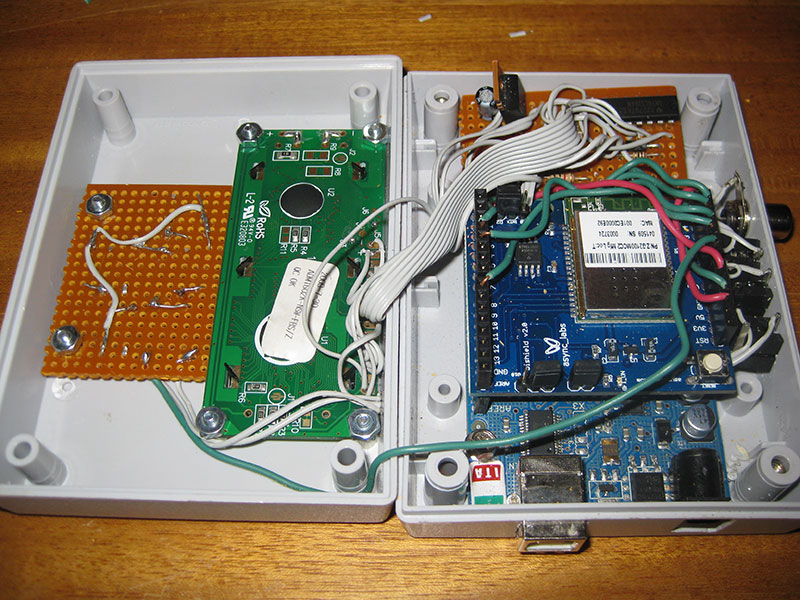
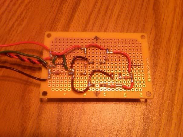
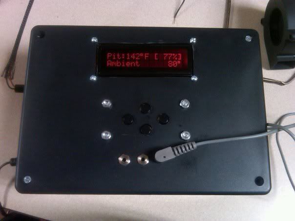
Version 2 of my homebrew controller


Originally posted by Ben B.:
Oh man, that is an even better option, if you do please share your schematic and instuctions.
If you look on their Wiki they already have the schematic and board files for Eagle. I looked at modifying it to use through-hole components and getting a PCB made but that was $24.18+shipping so that wasn't all that economical once you add in probably $40-45 for the components (including the flash chip) with shipping.

For $40 to have a test board isn't too bad considering I still have to support my Dad's version I made. I'd like to move to the router-based version but the router seems like much more CPU power but not enough to do cool things with it like pushing out live moving graphs and such. I really haven't had much of a chance to work with it though.
 
.... I looked at modifying it to use through-hole components and getting a PCB made but that was $24.18+shipping ....

I am building my heatmeter on stripboard $5.00 and no spaghetti on the back side. when I get it done Ill post pictures
check out this.
http://www.marlwifi.org.nz/files/StripboardMagic.zip

If you can get the through hole chips the rest is easy.
edit: OK how do i post pics?
 
woohoo!
I have a stable system all the menu buttons work, ambient,pit and food 1 are working, the buttons are on stripboard.
shift reg and probe jacks are on bread board. on to the blower circuit.
 
gerry, if you like doing this sort of virtual development, you might look into fritzing as suggested much, much earlier in this thread.
from what I can see fritzing != Stripboard
I am posting a higher level link not just the software link http://www.marlwifi.org.nz/other/stripboard-magic for info on how it works, I am building all my circuit cards on it . Stripboard can be layed out with out the software all you need is a 3mm drill and some inginuity.
 
can anyone offer some words of wisdom for transferring what I've got off the breadboard. If I've got one +5v out on the arduino and lots of components to send that to, whats the best way to go about it?

It makes sense to me to break it down a bit, ie there should be a 5v line from the arduino going to the board my buttons are on and the other board I'll have with the shift register and blower circuit, but whats the best way to take a single 5v line and send it to all the resistors in front of the buttons? I'm guessing its bad practice to try and solder FIVE wires together in a single joint. Seems safer to only be soldering two wires together at any one time would be the best way to go about doing it, but I'm having trouble visualizing how to split up the 5v/GND effectively to the components on a board.

Any advice would be appreciated
 
I try to daisy chain as much as possible, taking 5V to one component then running that to the next one and so on. I try to orient components such that either their power or ground leads are 1 or 2 perfboard holes away from another power/ground and then just use the lead of the component to connect it. For the button resistors I put 3 of them together and the fourth I ran a wire to, based on how I had laid out the resistors.

I had one 5V and one ground line going to the "daugherboard", i.e. the one with all the HeaterMeter components on it. Then from there, there is a power/ground pair going with the data wires to the LCD. Finally, the buttons are attached to the LCD's power/ground.
implementation-3.jpg
 
button board
edit: after many attempts to post pictures hopefully this will show up this is my button board. I am still laying out the rest of the circuit. notice the 2 tracks that are broken on the back side.
E10 and G10.


DSCF0571.JPG
DSCF0572.JPG
 
alright i have a question and I went back in the thread to try and figure it out but I can't seem to find what I'm looking for.

In Ed's schmatic ther eis a 1k resistor on the CLR of the shift reg. Is this necessary?

Also, IC1P below the shift register is just the cap that should go across pins 14 and 7 of the shift register correct?
 
Well phase 1 of ATC is done. Just waiting on the probes from the maverick to come in, they should be here tomorrow. And I need to come up with a mount for blower. But here it is all together.

199490_10150160787342603_696732602_8114908_1054096_n.jpg
 
Originally posted by Ben B.:
Well phase 1 of ATC is done. Just waiting on the probes from the maverick to come in, they should be here tomorrow. And I need to come up with a mount for blower.
Lookin' good! My Dad managed to crush the blower mount I made for him in some sort of 3 Stooges routine that involved him tripping on the cord then stomping on it, so he built a completely new one. I should have taken a picture of it but it was just a conduit coupling (like this, not this one) that he hammered slightly flat then screwed the other end into a flat piece of metal. The fan slipped in and was epoxied in place. Total construction time was around 10-15 minutes he said. Just another alternative design.

Ed, I'm still planning on making a DD-WRT version, but haven't had the time to switch to it, considering how much I'm still playing with the original. Also the winter here ended a couple of weeks ago so I've been spending a lot of time landscaping the house (sarcastic hooray). I'll get to it!
 
Well phase 2 is going to be me attempting to make my own WiShield. I think I will need to order another Arduino though so I dont have to keep tearing my newly finished ATC apart. Hopefully building a WiShield isnt too complicated.
 
Originally posted by Ben B.:
Hopefully building a WiShield isnt too complicated.
The main complication is the fact that the Arduino pins aren't spaced properly, the distance from D7 to D8 is 0.17". If you build on any perfboard you're going to have to drill your own holes for the pins to go through to get them to mate properly.
 
Originally posted by Bryan Mayland:
<BLOCKQUOTE class="ip-ubbcode-quote"><div class="ip-ubbcode-quote-title">quote:</div><div class="ip-ubbcode-quote-content">Originally posted by Ben B.:
Hopefully building a WiShield isnt too complicated.
The main complication is the fact that the Arduino pins aren't spaced properly, the distance from D7 to D8 is 0.17". If you build on any perfboard you're going to have to drill your own holes for the pins to go through to get them to mate properly. </div></BLOCKQUOTE>
Offset headers will take care of that check out http://www.sparkfun.com/products/9374
 
Originally posted by Ed Pinnell:
I'm more into do-it-yourself. Why buy it when you can make it yourself?
Oh that is a good solution there. I've seen some other bent-pin ideas which were bad because they raised the shield a little because the bend was below the plastic part. This seems like it would work even better.

And seconding what Ed said about building your own Arduino. It is about $10 worth of parts through Digikey/Mouser or I'd recommend the RBBB for only $13. I have something similar I use for my breadboarding projects and is half the cost. You'll need a USB-Serial programmer though, which will double the cost for the first one.
 
OK help me understand why I would want to go wireless.
Ed said a while back that the Arduino only knows how to do serial only anyway.
Am I correct in my understanding that the WiShield adds flash memory so it stores all of the data needed to build the cool looking web page and the data needed to build the graph?
Its not like we are moving these things about when they are cooking.
If I wanted to hard wire about 25- 30 feet of Cat5 line and try to do a I2c or RS422 com line I would be into it for ~15 bucks. I could do all the graphing I wanted on my desktop. Is this feasible? I think the flash is more important than the WIFI so you can store data.
What am I missing?
 
My whole reason for wanted to build a wishield is 1, the guy who runs asynclabs has never responded to any of my emails and 2, because I want to be able to use the code that Bryan has already done an awesome job with. I know it probably isnt that hard to modify the code to work with a DD-WRT router, but I would like to get the original design working before I get into the fancier stuff(icing on the cake).
 
I'm like a woman and need to make up my mind. But I just called my dad and asked if he still had his older linksys router and he does and its not in use. I am going to run over thier today and make sure it will work with dd-wrt. Ed, any chance you could could maybe post a sperate thread on how you went about getting your arduino to talk to the router? Even just links would help as it looks like in order to keep this thread clean you removed some of your older posts to avoid confusion.
 
Originally posted by gerry m.:
OK help me understand why I would want to go wireless.
Ed said a while back that the Arduino only knows how to do serial only anyway.
Am I correct in my understanding that the WiShield adds flash memory so it stores all of the data needed to build the cool looking web page and the data needed to build the graph?
Its not like we are moving these things about when they are cooking.
If I wanted to hard wire about 25- 30 feet of Cat5 line and try to do a I2c or RS422 com line I would be into it for ~15 bucks. I could do all the graphing I wanted on my desktop. Is this feasible? I think the flash is more important than the WIFI so you can store data.
What am I missing?

I want to be able to monitor my food temps from inside on a smartphone and don't want to have to fool with having to run a whole PC just to do it. We also cook competitions and being able to walk around away from the pits and monitor it or be in a trailer with AC is desirable but don't want to lug a pc around.


Back
Top