Version 2 of my homebrew controller


...and one other question about the HM schematic.

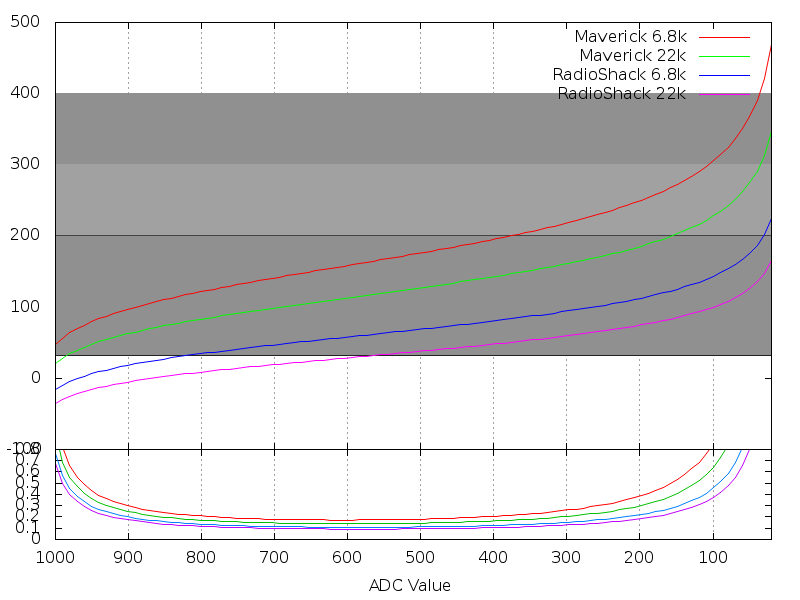
I can't figure out why R13 (which is the balancing resistor for the ambient temp probe) is a 22K resistor. The way I understand that voltage divider theory, a balancing resistor like that should be (roughly) equal to the resistance of the thermistor at the center of the needed range.

And since we're using a 10k @ 25C thermistor, I was thinking that a 10k balance resistor would work better.

The most likely reason I was thinking for using a 22k here would be to reduce line numbers in an order (i.e. lower cost) figuring that it's close enough. Is that it? Or is there something else going on that I don't see?
 
I used 22k ohm resistors on the thermistor dividers because that is what Bob used in his initial project. I think this value was chosen because that's what the measured resistance of these resistors is in the Maverick series devices. In retrospect this is probably the wrong value. You should select a resistor that helps push the response curve of the chosen thermistor into the most applicable range.

If you check this graph I made here, you can see the Maverick probes, with a 22k ohm resistor give the most accurate response between probably 50F to 175F which is great for measuring food temperatures for the average person. However as you're passing 300F, you start to lose resolution quickly such that each 1/1024 of the ADC is like 1F. If you used a 6.8k, instead you'd push that point closer to 400F. The reason you can't just use a 1k ohm resistor is that the lower you go the lower the overall accuracy of the system is.
steinhart.png


If you're asking why we don't use different values between the ambient sensor and the probe sensors, the answer to that is just that it saves code space to use the same value for all of them. That and the Ambient sensor is sort of useless anyway if you mount it on the PCB because of the heat created inside the box by the electronics. Ed's got the right idea that it needs to be run down to the fan inlet.

Also I just realized that the HeaterMeter+Graph demo page wasn't working for anyone not in my house because I had a reference to a local web file in it. Should be working now. Also I messed around with it some more and the web server serves data intelligently such that if you've got less than 1hr of data you get up to 600 6 second average points, if less than 5hrs you get 600 30 second average points, on up to 20hrs.
 
Originally posted by Ed Pinnell:
Wireless food probe v1.0 - single probe version
Looking good as always, Ed. Hey let me ask you. If you have like a dozen of those RFM12s all running at the same time, do they just talk all over each other or is there some sort of media access control?
 
Originally posted by Ed Pinnell:
Wireless food probe v1.0 - single probe version

Ok, I just looked back a few "chapters" in the thread here and I don't see anything mentioned about this. It looks awesome Ed! What is it wireless to? Where is it feeding the data back to?
 
Originally posted by Ed Pinnell:
John, first and foremost, this project is Bryan's and we are all fortunate to have him lending his considerable talents. Having said that, I am much more of a hardware guy and I get the most satisfaction out of building something with my hands, and I tend to put off the software end of things because I am not very good at it. Naturally, I lean towards a hardware solution whenever a technical issue comes up, so during the WiFi topic we were discussing Bryan mentioned the potential of using a router, I was all over it.

I couldn't agree more Ed. Without Bryan's handywork on the code this thing wouldn't be anywhere near where it is today. Don't sell yourself short though. You seem to have a perfect balance of hardware and software experience. I was pretty active on the same thread when Bryan tossed out that idea of using a router. The amazing thing is that you took it from idea to reality within just a few days! I think that blew us all away.

Basically, the RFM12B transmits the food temp and the battery state to the ATMega in the router. Because each RFM12B is capable of transmitting as much as 66 bytes of data, you could conceivably connect as many probes and/or sensors wirelessly to a single HeaterMeter as your heart desires. I've had a brief offline discussion with RJ and from what little I know about his pellet feed system this sounds ideal for what I think he wants to do.

Wow! That is awesome! Very cool feature!

I suggest, though, that a new thread be started here soon because of the length this one has grown to.

I agree, although it would be nice to talk about these and other projects we're all working on and tvwbb may not be the place for that at all. For example, I temporarily borrowed my Arduino and WiShield to make a chipmunk havahart trap to rid my garage and garden of chipmunks. I no longer have to check the trap to see if I caught anything. It will send me a text message when it springs and turn on a special light I have setup in my house. If you have any suggestions on where we could talk about such things let me know. I would be happy to setup a forum on my personal web site for stuff like this if you think it might be useful, but then we have yet another login, another site to visit, etc.
 
For those interested in reading this whole tread, you can download a PDF file of everything to date HERE for offline viewing.

It's 242 pages long and where possible, all of the images linked within posts are shown full-size.

Sorry, but I had to ZIP the PDF. It is less than 1/2 the file size when zipped and I don't want to totally kill my bandwidth.

It's compressed using 7-zip which is a free download from HERE (I highly recommend 7-zip if you're not already using it).

Enjoy!
 
I must be buying wrong when it comes to construction materials for the blower. My recent totals came out to:

$9.95 - silver solder and flux founding in the plumbing section

$5 - small sheet of 22 gauge steel

$5 - emery cloth

$5 - paint (guessing here haven't bought it yet)

Considering the fan cost $13, that totals out to

$38 in parts for me, and auber's got a fan with everything already made for $46. This just *can't* be right can it? Where did you guys find your stuff and how much did it cost?

Question #2 - how did you go about bending the sheet to form the 'tunnel'?

Question #3 - how did you seal the blower to the tunnel? Seems like no matter how precise you were at bending the metal there would still be gaps.
 
Whoops, I just noticed that my PDF is missing the last set from the thread (page 24), and page 14 is out of place. I will fix it tomorrow for those interested.

John
 
I don't want to get too far off topic, but that blower mount I referenced is built here in the good ol USA. I like building stuff so that's what has drawn me in here, but admittedly my forte has nothing to do with metal work.

I guess maybe I'm doing all the wrong projects, but I've had very few projects that ended up costing more than purchasing someone elses time/expertise. Everyone's contributions here have given a lot of people an option they never would have had before. I never could have gotten this far on my own, i'm definitely 'standing on your shoulders' and I don't mean to be insulting on cost, I just don't want to pay $5 for a lil piece of sheet metal if I can buy it somewhere else for $1, ya know?

I guess my post came more from surprise than anything else. considering the cost of all the other materials, the piece of metal the fan mounts to is the costliest item this side of the arduino. I didn't see that one comin
 
Originally posted by Ed Pinnell:
LASTLY: I kinda got carried away with the show and tell and I apologize for the disruption. This has nothing to do with the evolution of the HeaterMeter project and doesn't belong here. I will take it down in a couple of days, so if there is anything you want, get it while it's here.
No way, Ed, your pictures are always great. You should really consider starting your own thread for the LinkMeter with wireless food probe and cool custom made fan bracket and all that. That way we can always go back and marvel at your designs and see the work log as you did it. I think it would be a tremendous inspiration to others who are looking for something similar. I probably should also start a HeaterMeter thread with a First Post that can remain up to date and contain links to other posts in the thread with good information.

Also thanks for the information about the RFM12B, I want to build an outdoor temperature probe for my A/C at some point and it seems like more fun to do it that way.

As Ed has pointed out, a lot of the cost of building a controller comes from using things you have on hand. I mean I had all of the passive components needed, breadboard, some crappy tools, a blowtorch, and some sheet metal sitting around. If sheet metal isn't something you have available, go for something else. If you only have a 9V power supply, that'll probably work fine too if you adjust the PID coefficients.

Just like Ed I'm doing this for fun more than cost savings. That idea clearly went out the window long ago.

I just wish my board layout skills were as good as Ed's. I spent about an hour trying to layout the parts for a replacement WiFi board then finally gave up and just started soldering things to breadboard. An hour or two later I ran into trouble when I ran out of space!
 
Originally posted by Ed Pinnell:
Hey, I was going to tell JD, you made your fan bracket out of cardboard...is that still holding up for you? And your Dad cobbled one up out of a conduit fitting...any details on that?
This is true! I still use my cardboard fan bracket. I should say "cardstock" because it isn't like corrugated cardboard it is thin. Thin like cheap shoebox cardboard. It is still holding up, despite being a lot browner than it started out. The scotch tape is starting to peel away too. It definitely served beyond what I expected it to, which was one usage. A couple new pieces of tape and it would certainly last another 15 cooks.

I should have gotten a picture of my Dad's rig. It was just a conduit fitting, crushed to be rectangular on one end, then epoxied to something that slid into the vent hole.

I like seeing "what you did today" though. I find it interesting how you design the boards, fit them into things, build a little bracket, things like that. It gives me ideas on how I might solve similar problems. I have very little creativity in that area and you're just brimming with it.

Anyway, if you need any quick help with the software, you have my gmail address. You're welcome to use anything I've got, and I can provide the scripts I am using to do my basic router stuff now if you're ready for that.
 
Ed, where did your post go? I saw it today at work and now it is gone! You with all your post deleting. I'll send you a gmail so we don't fill this thread with our nonsense.
 
Originally posted by John Mangan:
Hey guys, I'm still alive. Watching the very active thread here. I LOVE some of the improvements that Gerry has made to the project.

Me too!
icon_smile.gif


Keep up the good work, folks.
 
And for those wondering what a ZeroG wireless card looks like with through hole components:
f2giq.jpg


Except not like this one because some moron soldered all the wires on the left side backwards. Well semi-backward in that the wires are in the correct order but instead of connecting them to pins 36,35,34,33,32,30,29,28,25,23,21,20,19 I connected them to 36,35,34,32,30,27,26,25,23,22,21,20,19.

So, yeah, I have to rip the whole thing up and do it again.
 
That is just awesome looking RJ. I can just imagine the first time I go to pull the USB cable out I short something and fry the whole shebang.

I'm going to make a new thread for the HeaterMeter project, just so we can have all the relevant info in first post with an updated schematic and the latest software and all. Even I can't find things in this thread.

For anyone looking for a WiShield, there's a company called LinkSprite who makes a product called "CuHead WiFi Shield for Arduino" which claims to be AsyncLabs comaptible and their description is a copy-paste from the AsyncLabs website. Checking their schematic though, I see they added a LiPo charging circuit but removed the dataflash. While you can use this to serve the current temperature, without the dataflash you do not have the storage / progmem to have any more than a <2KB web page.
 
i had a question i was hoping one of you guys could answer. Whats the difference (besides the obvious) in the number of termination wires on a blower?

I was looking at this blower instead of the one on the parts sheet, and it looks very similar except the number of termination wires is 4 instead of 2.

http://search.digikey.com/scri...ail&name=603-1244-ND

My google searching failed to tell me what other functions those extra wires serve... anyone here know? (paging Ed)
 
Alright, new question. Has anyone run against a maverick during their cook?

Its strange... I swear I busted out the Maverick while everything was room temp and compared the readings between the HM and the Maverick and everyone agreed within a degree or two, but now I am doubting myself.

I've got the HM and the Maverick monitoring the pit, and over time their "agreeance" has gotten further apart. At first it was about 10*, which seemed high but manageable just for testing sake, but now the difference is 30* (HM 230*/M 260*)

I've got the probes literally right next to each other and when I plug the HM probes into the Maverick, the reading doesn't change (ie Maverick temp stays the same no matter what probe I plug in)

Anyone got any ideas on where I should check first? Off the top of my head I'll be looking at the voltages coming off the probe.

I checked the resistance on them as installed and they all read 21.6k. NOW they both aren't even close to 22k. I ordered the same ones in the spec, but clearly somehow they crapped out... the only thing I can think to do is swap them out with 1/4w ones. I've got additional 1/8w ones though, maybe I should swap them in first?


Back
Top