Troubleshooting HM hardware/PCB network issue


Michael Kennedy

New member
Hello - long time lurker and admirer of all the expertise on this forum. Built my HM 8 yrs ago; the advice/guidance has been invaluable, with hundreds of BBQ-satisfied family & friends served.Thank you!

Am hoping someone can help with what I think is a hardware-related network issue. I’ve read the various threads related to troubleshooting network connectivity. This feels a bit different.

I have a 4.3.3 build with RPi 3A+. Although the unit has worked flawlessly for 8 years, now it will not establish a wifi or wired connection with my router. The LCD screen no longer displays the “Network Connection” option, only pit temp > Manual fan > Reset config?

The unit powers up just fine. Nothing changed on the network settings prior to this issue.

Additional troubleshooting options I’ve tried:
- Complete SD erase/reformat, ensure only 1 partition, re-flash with v15 HM software. Nope.
- Tried connecting directly to HM via RPi USB -> RJ45. No luck. Tested USB-RJ45 adapter alone with RPi/Raspbian OS card and it connected just fine. In this config RPi connects to WiFi normally.
- Tried connecting HM to laptop via ethernet cable/USB adapter. Nothing.
- I even tried a different RPI 3A+ in case it was something obscure that I was missing. Nope.

Just prior to its demise - during its final cook - I did notice some odd, intermittent connectivity issues. The unit would go offline for a bit (showed up on hm.com/devices but had an error). A minute or so later it would come back online.

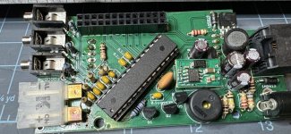
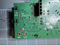
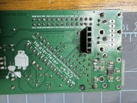
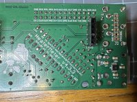
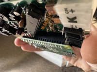
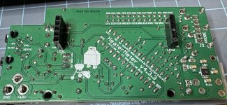
This would seem to suggest a HM hardware issue. It’s had ~ 8 years of hard living ; ) Pics of the board attached. I did a thorough scrub of all solder points with 99% isopropyl in case some old flux/goo was the issue.

Are there particular Tx/Rx PCB pins I should double check or re-solder? I’d hate to have this ol’ gal give up the ghost.

Thank you in advance!
Mike
IMG_5344.jpegIMG_5342.jpegIMG_5339.jpegIMG_5338.jpegIMG_5343.jpeg
 
Strange problems. They only question I have is, did you try a new tested good power supply that has a minimum of 2 amps. If your power supply develops high levels of noise, that can mess with the device. Check power supply with dmm set on ac and see if there are high levels of ac. Noise needs to be in the double or single digits. I like to see 50mv max and lower the better. Also, when connecting the ethernet from HM, did you try connecting to an unused port on your router. Sometimes connecting directly to laptop will have issues because of port setting conflicts. Connecting directly to a router ports, for me, has always worked.
 
If it worked for 8 years then it may be a hardware problem especially if its seen a lot of vibration or temperature changes.

I would recommend the following:
1 - Inspect the solder joints closely to see if any are cracked. Once the solder cracks, it will eventually become an open circuit. If you have a schematic, follow the circuit path for the wifi.
2 - Inspect the ceramic parts (resistors, capacitors) for cracks as will.
3 - Remove and inspect any part in a socket as contamination can build up in the socket connectors.
3 - Start the board then tap on it as this can sometimes make an open circuit rear it ugly head.

Keep us posted on progress….
 
Gary and Mark - thanks for the suggestions!

This unit has been used extensively in cold weather conditions (Chicago!), so a micro crack is definitely a possibility. I took a look at all the joints and ceramic parts under a magnifying glass. Did not see any cracks. All of the socket connectors and pins appear to be fine (nothing wiggling, nothing corroded to the naked eye).

Gary - the ethernet test direct to HM was performed from my eero wifi router direct to the board. For a positive control, I tested the same cable to my computer. Worked fine. I also looked at the power supply. DMM reads 12.1V.

In terms of testing AC on a DC supply, is this simply moving DMM selector to AC voltage?

I’m no electrical engineer, but if RPi has no issue connecting to wifi/internet, the issue must be comms between RPi and HM. Per this thread I tested continuity between Rx and Tx lines on the PCB. Continuity was solid, so that circuit on the board appears OK.

Replacing the AT Mega chip seems to have solved the issue in that case. It’s a $3 part, so I ordered one just to see.

If this doesn’t work, I’ll try Mark’s tap-tap-taparoo strategy. ;)
 
Update:
(1) Received the new AT Mega (ATMEGA328P-PU) from Digi-Key, popped it in. Booted up. As one would expect, HM LCD showed all black bars - which should resolve once RPI fully boots and runs the script to flash ATMega. However, this never happened even after 30+ min.

Noticed the RPI LED indicator lights were in error mode. The green indicator light blinks in a 4-slow, then 7-fast repeating pattern
- 4 flashes: start.elf not launch-able (corrupt)
- 7 flashes: kernel.img not found

(2) I verified the HM SD card has both start.elf and kernel.img files. I reflashed the SD card with the current v15 HM software for RPI3A+, verified verified both start.elf and kernel.img files were present, and tried again. Nothing. Also tried a brand new SD card with the latest development release (1/3/2022). Same LED kernel errors.

To re-test the RPi, I took a "failed" SD card with HM software, re-flashed with Raspberrian. RPi Booted up, wifi and USB ethernet work perfectly. I can connect seamlessly via ssh and VNC viewer.

In fact, if I boot up RPi with the HM board attached, the PI works normally.

(3) The powersupply does not appear to be an issue, as I get identical results whether power is from HM barrel plug or RPi micro-USB.

Is there something on the HM PCB board that could cause a startup kernel error on the RPi?

And I did try the "tapping" method. No success.
 
Mark - I tried cleaning pins with an acetone Q-tip. Used compressed air for female connectors. No fix.

I discovered something interesting, though. While scanning a few other hardware-related threads, I found one involving fan/servo issues.

@Steve_M proposed a simple test to check the fan circuit: using HM board alone (no RPi), remove AT MEGA, connect the fan RJ45, and plug-in HM via 12V barrel. If the fan comes on, there's a hardware issue. I thought, "Well, at least this will show one circuit is intact."

The fan came on. This appears to be trouble.

I re-flowed a few prime suspects (Q1, Q2, Q3), but unfortunately, that did not fix it. The pins for each of these components appear to be intact, though it is hard to see underneath.

I re-checked the ATMEGA solder joints, did not see anything (I had re-flowed these yesterday). For fun, I put the old AT MEGA back in and powered up to see if I was still getting the error where the display would not show any wi-fi or network info. That's exactly what I found - the same situation I started with.

It sounds like I might need to get deep into the weeds, testing individual component continuities/voltages.

100% open to suggestions on what to try next - or if I should say my goodbyes and let 'er go to the great pit in the sky...
 
... the core issue seems to be that the 3A+ RPi alone, no HM, fails to boot with any v15 HM build (Heatermeter AP, AP, or Client) or the dev snapshot.

Kernel panic each time (RPI green LED 4 slow flash, 7 rapid).

This is not normal, right?
 
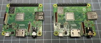
A bizarre new twist: The new 2022 RPi 3A+ I've been using to help solve this issue appears incompatible with HM v15 (or other versions). I've tried every possible HM version on the 2022 RPi. Every single one causes a kernel panic.

However, When I took the SD out of the 2022 RPi and put it into my older 2018 version (which is the one I've used for 5+ years), the RPi fully boots. I can access the web interface. Same model RPi, Just different manufacturing years.

I'm wondering if others have seen this? Pics of the two units are below. The right one works, the left does not. A quick visual inspection does reveal some differences (lower left quadrant of the two devices).

IMG_5453.JPG
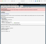
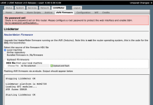
Unfortunately, I am now dealing with the "AVR Fuses Error." Several attempts at re-flashing did not fix it. Will go back and re-test continuities/voltages at the various locations in that thread.

This is progress, right? ;)

Screenshot 2024-02-18 at 2.44.02 PM.png
 
Continuity/Voltage test results:
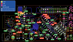
Per Bryan's recommendation, I confirmed continuity between MOSI, MISO, SCK, and RESET from ATMega to pi header were good.

However, under 12V barrel power detached from the Pi, a number of voltages were off. Red boxes indicate measured voltages significantly different from expected, including at several ATMega pins.

Screenshot 2024-02-19 at 8.46.19 PM.png

Good news is the 12V-5V OKI converter and 5V to 3.2V are giving expected results.

I am pretty much an amateur when it comes to building/troubleshooting PCB circuits. Does anyone see a key component that, if replaced, might bring things back into balance? So many components are connected, that I'm wondering if it could be one issue that is mucking up the system.

Thanks in advance!
 
When checking power supply for ac, yes select ac and if you have a mv selection, select that. Anything over 300mv is an indicator supply is cheap or bad. Also make sure to use at least a 2 amp supply. I would also start over using original Pi. Hope you bought more than one ATMega chip . Install another new chip on HM board and mount it to Pi. Make sure you are getting the HM pins into the correct Pi header. Same goes for display board. Plug in PS and go from there. One other thing to do is start with a brand new un-used sd card. Format it and then install HM OS. I use "SD Card Formatter" to format and then transfer the HM OS to card using what Brian recommends on the GitHub link. I have run into flakey SD cards more than once and that always causes issues. I would start with a new card for sure
 
Gary - Thanks for the suggestions. I tested ac. It’s at ~20mv, well below the 300mv threshold. 4A power supply. HM has run well with this unit since I built it. Unit also powers fine using RPi microUSB.

Tried SD Card Formatter to prep the card. Unfortunately, no success. I don’t think it’s a SD card issue. Have tried 4 in total, 1 of which was brand new out of the package. Each of these works fine if re-flashed with Rasperian.

Summary of where I’m at:
(1) RPi is good (v2018). v2022 and HM v15
(2) HM/Linkmeter boots, pulls IP address
(3) HM/Linkmeter web interface loads fine
(4) HM LCD shows all black boxes; none of the LEDs are lit
(5) AVR reboot does resolve.
(6) AVR manual re-flash via LinkMeter>AVR Firmware> Bundled Firmware. or > Local Machine results in "AR Fuses Error"
(7) Positive continuity between ATMega/Pi header for MOSI, MISO, SCK, and RESET
(8) Re-flowing solder connections unsuccessful.
(9) RPi-HM connection pins appear correctly seated

At this point, I think it has to be a hardware issue. I priced the suspect parts (capacitors, resistors, ATMega chip and holder, etc.) It's $25 all-in, including at least two extras per part in case I screw up. Cheap.

Any desoldering tips? :oops:

IMG_5481.JPG Screenshot 2024-02-24 at 10.17.29 AM.png IMG_5483.JPG
 
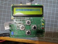
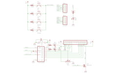
Looks like to me from your pics that the issue is on the display boards. I would replace the driver chip on the display board. Make sure your push buttons smoothly click. If one is stuck on, that could be your problem. Check across switch terminals to make sure they are open or show at least some resistance. O ohms is a problem. these switches spst n.o. switches. From your pics you posted your solder joints all look good to my eyes. Attached the schematic for display in case you do not have it. Heatermeter LCD board schematic.png
 
Q: Even without the LCD board connected, I can’t flash the AVR via Linkmeter. So it would seem that the issue is with the main board, not the display board?

Because there are a bunch of things I’ve swapped out, It might be helpful to recap results.

(1) Original issue: RPi(v2018), ATMega (old)
- RPi boots up
- Linkmeter web interface unreliable, 95% “Not found.” On the occasion when I did connect…
- “AVR Fuses” error when attempt reflash via bundled or latest snapshot online firmware
- LCD displays “Pit temp > Manual Fan > Reset Config?” But no “Network Connection” option. Pit temp works
- LCD board buttons work

[reflowed solder connections, cleaned flux, inspect resistors, capacitors, etc.]
[voltage/continuity measurements as above - potential issues found]

(2) RPi(v2018), ATMega (new)
- RPi boots up
- Linkmeter web interface RELIABLE via WiFi. Unsure whether ATMega or reflow/clean helped
- “AVR Fuses” error on reflash attempt
- LCD all black bars

[back to original ATMega]

(3) RPi(v2018), ATMega (old) - original hardware
- RPi boots up
- Linkmeter web interface RELIABLE (suggests reflow is what fixed WiFi issue, not ATMega)
- “AVR Fuses” error on reflash attempt
- LCD displays “Pit temp > Manual Fan > Reset Config?” But no “Network Connection” option. Pit temp displayed
- LCD board buttons work

[Tried new (2022) RPi]

(4) RPi (v2022 new), AT Mega (old or new)
- Kernel panic v15 HM. End of story

This “Fried HM” thread feels very similar to the issues I’m seeing in terms of black LCD bars and an inability to flash AVR.

I ordered 4 new ATMega chips from DigiKey, using the exact link in the GitHub 4.3 HM board hardware webpage. Will try swapping in a new one first…
 
Well, I desoldered and replaced all the components giving wonky voltages (see post #11).

This included several resistors, the MOSFET, 100uF and 0.1UF capacitors, inductors, ATMEGA (x3), the IC socket, PI header, and LCD PCB header. I'm sure I'm forgetting a few more.

Nada.

It would seem there's an issue with the PCB board itself. I've looked at it several times under a magnifying glass and can't see any obvious issues.

I'm sorry to have to retire my trusty HM, but it had a great run!


Back
Top