RaspberryPi + LinkMeter blue sky discussion


Originally posted by Bryan Mayland:
Whatever you do don't use the schematic in github labeled "DO NOT BUILD".

I don't see the "DO NOT BUILD" in the github. Let me know when/where you put the working version. I am going to have to find smd versions of all the components which shouldn't be hard but will be time consuming. I did buy some nice tweezers so this should be good and frustrating!

I did get most of the way through building a Linkmeter version in smd but stopped because I saw the Pi coming!
 
Originally posted by Dave S (GeoDave):
I don't see the "DO NOT BUILD" in the github. Let me know when/where you put the working version.
Ah yeah I didn't push it to github. It's there now if you want to see the bad version. I've also removed the reset button in the upcoming version because it's not needed for programming. You can still short the one of the reset pins to ground if you need it, or use the software reset from the Pi side. But at least you can get an idea of what's needed for your board.
 
What does the paid version of Eagle cost?

I can't spare all that much right now, but I'd be willing to donate if prices are reasonable.

EDIT: Individual version is $169! Ouch. I was hoping more like $50.

Nudge it is!
 
Originally posted by Bryan Mayland:

I had wired the Pi's hardware chip select, CE0 to the /RESET pin on the ATmega thinking it would be able to generate the requisite signals to put the AVR into programming mode. However, the SPI kernel driver always de-asserts CE0 at the end of each SPI "message", if there's no other message waiting to be sent. To program the AVR you have to hold the /RESET line low the whole time so CE0 was unsuitable for this application.

Got it. I notice the software reset circuit on PD7 is gone from the HeatermeterPi schematic. Can you explain how that circuit worked with the Linkmeter board and how the wiring to Pi's hardware chip select is different? Was the previous software reset used by the linkmeter to put the AVR into programming mode? I am trying to get this straight in my head.

Originally posted by Bryan Mayland:
Whatever you do don't use the schematic in github labeled "DO NOT BUILD". It has a critical flaw in that the 5V switching regulator's pins are connected backwards (actually they're built backwards) which will connect your Pi up to 12V.
Ehhh...I am having trouble seeing the error. Are you talking about the part labeled "OKI-78SR-5" where the "KA7805AETU" was previously? I am looking at the 7/20/2012 6:01am schematic. It looks like you reconstructed the schematic from scratch kinda.

THE ALARM! I see the buzzer in the design. What about a text message to my phone? I am never close enough to hear the thing buzz. I know I know you asked for comments on the alarm a while back but I was MIA for a while because of job stuff.
 
Originally posted by Dave S (GeoDave):
Got it. I notice the software reset circuit on PD7 is gone from the HeatermeterPi schematic. Can you explain how that circuit worked with the Linkmeter board and how the wiring to Pi's hardware chip select is different? Was the previous software reset used by the linkmeter to put the AVR into programming mode? I am trying to get this straight in my head.
Yeah on the LinkMeter, there was only serial running to the AVR so to reboot it, you send "/reboot" and HeaterMeter pulls a digital line low just long enough for the the reset to activate. You're not supposed to do it this way but it seemed to work 90%+ of the time. The Pi schematic will have the the AVR's /RESET pin connected to the Pi's GPIO25 which allows us to hold reset as long as we like. The DO NOT BUILD schematic has it wired to the Pi's CE0 which proved to be unsuitable due to how the SPI drivers are coded (and probably all Linux SPI drivers).

Ehhh...I am having trouble seeing the error. Are you talking about the part labeled "OKI-78SR-5" where the "KA7805AETU" was previously? I am looking at the 7/20/2012 6:01am schematic. It looks like you reconstructed the schematic from scratch kinda.
Yeah the OKI-78SR-5. It looks right in that it is a pin-for-pin replacement for an LM7805, but the horizontal version of it is made to mount face down, which is the opposite of how the 7805 mounts so pins 1 and 3 are swapped. The LinkMeter and Pi schematics are mostly similar except with the serial interface, reset, and 3.3V shifting removed because the Pi version runs at 3.3V.

THE ALARM! I see the buzzer in the design. What about a text message to my phone? I am never close enough to hear the thing buzz. I know I know you asked for comments on the alarm a while back but I was MIA for a while because of job stuff.
Yes! The buzzer is in and working in the latest HeaterMeter code but there's no web interface for it yet. The notification system will incorporate making an web request or sending an email (which can be sent to an SMS address if your carrier supports it). The LinkMeter version can't send email if your mail server requires SSL encryption, due to the size of the libraries required to do so, but the Pi version does.

I've been spending all my time on the hardware side though, because of the high turn-around times on getting PCBs made and tested.
 
Originally posted by Bryan Mayland:
Yeah the OKI-78SR-5. It looks right in that it is a pin-for-pin replacement for an LM7805, but the horizontal version of it is made to mount face down, which is the opposite of how the 7805 mounts so pins 1 and 3 are swapped. The LinkMeter and Pi schematics are mostly similar except with the serial interface, reset, and 3.3V shifting removed because the Pi version runs at 3.3V.

So whats wrong with the existing 5V regulator circuit? The OKI-78SR-5 costs 8+ times more than the KA7805AETU. I see you also removed what I thought was a decoupling capacitor (C6 0.1u). Is this not necessary because it is a regulated output? Oh...and you also decreased the capacitance on C4 from 47u to 22u...I guess 47u was unnecessarily high?

Also, I mostly understand the 5V regulatory circuit. The only thing I am confused about is the 1N4001 diode. It looks like this diode would block the 12v from coming into the linear regulator or Dc/Dc converter. Don't we want that going in so it can take it to 5v? I am obviously missing something. Now that I am super familiar with the design, I am trying to learn the electrical concepts.
 
Originally posted by Dave S (GeoDave):
So whats wrong with the existing 5V regulator circuit? The OKI-78SR-5 costs 8+ times more than the KA7805AETU.
The 7805 is a linear regulator and the Pi specs say it needs 700mA. Add on probably 300-500mA for a USB WiFi adapter and the HeterMeter draw of of to 50mA and we'd be way over spec for the 1A regulator. Also because it is linear that means you need a 1.5A 12V wall wart before you even include the fan. The OKI is a switching regulator with 90%+ efficiency at that power level up to 1.5A. If we assume all the circuitry is pulling 1.4A that's only pulling about 700mA from the 12V wall wart, leaving 300mA for the fan with a readily-available 1A adapter.
I see you also removed what I thought was a decoupling capacitor (C6 0.1u). Is this not necessary because it is a regulated output?
C6 and C9 are just for stabilization of the 5V and 3V3 power lines. All the major circuitry now runs on 3V3 except for the LCD which has its own decoupling so C6 seemed unnecessary. The Pi has plenty of onboard decoupling and power stabilization on its 3V3 lines and we're adding a second 3V3 regulator (which should halve the ripple) so C9 seemed superfluous. All the power caps are going to be replaced with low-ESR versions too so they should be able to deliver power faster when needed.
Oh...and you also decreased the capacitance on C4 from 47u to 22u...I guess 47u was unnecessarily high?
Yeah 47u was the standard Arduino capacitor size which is pretty high, the OKI datasheet says 22u input if using low ESR caps so I put that in place, knowing I could get 22u 10V caps in 7mm height. All the power caps have been moved now though so I can use 11mm height versions and all will be increased to 100u or greater.
Also, I mostly understand the 5V regulatory circuit. The only thing I am confused about is the 1N4001 diode. It looks like this diode would block the 12v from coming into the linear regulator or Dc/Dc converter.
D3 is there to half to protect against hooking up 12V in reverse polarity and blocks current the opposite direction. Its second job is to prevent the fan from using C4, and dipping the input voltage to the 5V regulator which would make keeping a constant output voltage more difficult.

Whew. After spending all day redoing the layout I think I've got something I am happy with. The rules:
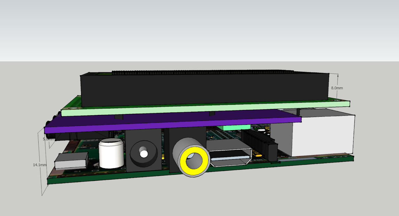
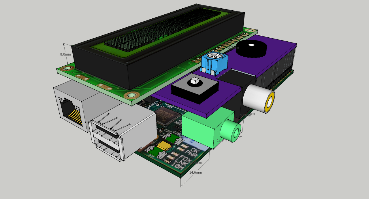
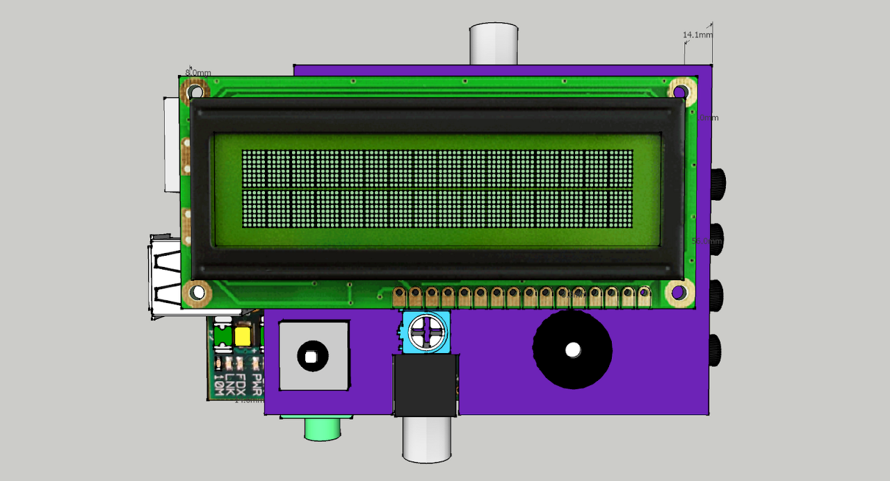
-- The board must be 4.1" wide, which is the same width as the Pi PCB and SD card measures.
-- The probe jacks must fit in a line
-- The LCD and button must be centered
-- The LEDs must be in a line and on an edge, facilitating the ability to have the stick up to the top of the finished device, or bent 90 degrees to stick out through the side of the device.
-- The Pi expansion header is in a fixed place.
-- All capacitors polarized in the same direction.
-- The Pi connector keepout areas, oh god the keepout areas. This was by far the hardest part of this project, keeping components out of the areas where the RCA and headphone jacks are on the Pi.

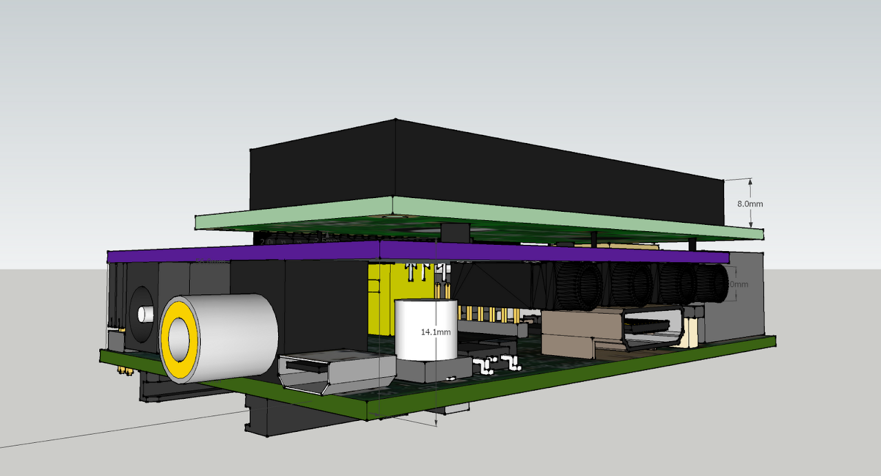
Looks like this now, 20mil power traces, 12mil signal traces, only 3 vias! I still have to do the silkscreen but I think that will wait for tomorrow, I've been working on this for 11 hours just today.
 
Thanks for the explanation! I guess the adjusting the power supply to meet the needs of the Pi was obvious. Check...I will try to find low-ESR smd caps. I wonder if I can find a smd version of the DC/DC converter...maybe not. I think I can squeeze it in since I am using smds for everything else. Nice work on the board!!! I will wait until you finish revising the schematic before I start on my board.

Here is my revised sketchups for my smd:

Concept12.png

This is a tight squeeze but I think I will be able to get them in. The RCA jack is going to elevate the board on this side by 0.7mm.

Concept11.png

I think I will have plenty of room to place the rest of the components.

Concept10.png

Button, piezoelectric, pot!

Concept13.png

These probes I found in the sketchup parts library are just about the same are yours...a little larger actually.

Concept9.png

Top view.
 
I got a more accurate sketchup model for the Raspberry Pi. It looks like the blower jack and power jack aren't going to work in their current location so I moved them around a bit.

Concept14.png


Concept15.png
 
That's really awesome, Dave, the renderings are fantastic!

I managed to resurrect my Pi setup this morning and I was excited to get back to testing the first board prototype. The SPI was still pretty wonky and the UART wasn't working at all. I ran around testing tons of pins on the oscilloscope and I discovered why. Another MAJOR problem with the PCB on github (befd54cf3ffbf630d8cc6118f0fa88b8c2673518). Can anyone spot what the incredible glaring problem is? Don't read the next paragraph until you've figured it out...

Good work! It is pretty obvious, isn't it? For the slow people, take a look at the ground pour polygons on the bottom layer. Look good right? Look at the one that the AVR sits on. Where does it connect to a ground polygon that is actually grounded? Nowhere. That's right, the pours aren't connected properly! This means that the AVR (and a couple of other smaller pours) are powered but not grounded. This actually works a lot better than you'd think it does, it actually sort of works some of the time. I soldered in some "blue wire fixes" to connect them up and everything works consistently now.

The next problem is that the Rx/Tx UART lines going to the Pi are swapped so they don't talk to each other. Not a hard fix.

Finally, and this may be a big stumbling block, the LCD works when the board is not connected to the Pi but does not when it is. The SCK line isn't wiggling. I've got the broadcomm SPI driver built into the kernel, and I'm hoping that if I build it as and unload the module, I can get the broadcomm to release the SPI lines to allow the AVR to be the master again. If not, it is back to the drawing board.
 
Originally posted by Bryan Mayland:
That's really awesome, Dave, the renderings are fantastic!
Yes but really it is easy. I created some of the parts but you can find a lot of parts in the sketchup parts library. It is great because it is super easy to learn and you can see where you will run into issues. I checked the parts library yesterday and someone added a dimensionally accurate Raspberry Pi.

Originally posted by Bryan Mayland:
Good work! It is pretty obvious, isn't it? For the slow people, take a look at the ground pour polygons on the bottom layer. Look good right? Look at the one that the AVR sits on. Where does it connect to a ground polygon that is actually grounded? Nowhere.
Did you just miss routing that wire? If so, it would be obvious if you were the one doing the routing because it tells you how many air wires are left. It isn't so obvious to someone who hasn't been staring at it for 11 hours.
icon_smile.gif

Originally posted by Bryan Mayland:
The next problem is that the Rx/Tx UART lines going to the Pi are swapped so they don't talk to each other. Not a hard fix.
Ahh yep AVR Pin 3 should be going to 10 on the Pi and AVR Pin 2 should be going to Pin 8 on the Pi.
Originally posted by Bryan Mayland:
Finally, and this may be a big stumbling block, the LCD works when the board is not connected to the Pi but does not when it is. The SCK line isn't wiggling. I've got the broadcomm SPI driver built into the kernel, and I'm hoping that if I build it as and unload the module, I can get the broadcomm to release the SPI lines to allow the AVR to be the master again. If not, it is back to the drawing board.
How do you figure this stuff out? I realize your are a computer programmer and you have a good understanding on how these systems work but how do you trouble shoot this? Sounds like the oscilloscope has been helpful...maybe I need one just for fun.
 
Originally posted by Dave S (GeoDave):
Did you just miss routing that wire? If so, it would be obvious if you were the one doing the routing because it tells you how many air wires are left. It isn't so obvious to someone who hasn't been staring at it for 11 hours.
icon_smile.gif
The restrictions on where things had to be meant that things had to be in non-ideal places. I've gotta run SPI bus to the AVR, the Pi, the RFM12B and the ICSP. 6 data lines to the LCD around those from the shift register. Serial to the FTDI, Pi, AVR. 5V for the LCD on both sides of the connector as well as the Pi. Blower support components before the diode. It was all too much for me to route manually so I would export the board, load it in FreeRouting, fix the rules because FreeRouting hates you, start the router then wait 10-15 minutes. Move a couple of components around in EAGLE, repeat.

The problem is that if you have your polygon pours down in EAGLE when you export, FreeRouting assumes they're all already connected because the EAGLE export lists them that way. FreeRouting doesn't fill the polygons, it leaves that for EAGLE. It works fine as long as the polygon isn't broken by a trace, which is the case when I did the button board this way. It all worked so well I didn't notice the couple of airwires in EAGLE with all the clutter. I found it by checking voltages and found that some grounds were anywhere from 0.4V to 1.3V higher when compared to other grounds. When I did a continuity check they failed so I brought up the old board rendering and zoomed in and slapped myself.

Ahh yep AVR Pin 3 should be going to 10 on the Pi and AVR Pin 2 should be going to Pin 8 on the Pi.
Yeah I sent the board off to fab without verifying this. It worked on my breadboard setup because I had it right there. Also my ground was good on the breadboard. I'm so glad I built that first and got hmdude working because this would have been a real pain to debug from the software side only.

How do you figure this stuff out? I realize your are a computer programmer and you have a good understanding on how these systems work but how do you trouble shoot this? Sounds like the oscilloscope has been helpful...maybe I need one just for fun.
I reduced the equation by removing the HeaterMeter from the Pi, it still runs standalone if a Pi isn't attached. I have an LED with a resistor soldered on one of the legs and I just dropped that into the ICSP header between SCK and GND. It should blink a couple times when Optiboot flashes the LED (which happens to be on the SCK line on the Arduino platform). Once HeaterMeter boots, when it updates the LCD it blinks the LED as data is transferred to the shiftregister (it blinks at like 2MHz!). That was happening so I press-fit an LCD into the header and wedged my finger into it juuuuuuuuust right and every couple boots the LCD would say NO PROBE. Connected it back up to the Pi and presto change-o the LED stopped blinking. For good measure I looked at it in the scope and SCK just stayed low the whole time after bootup.

I do a lot of LED-based debugging because my scope doesn't have any sort of advanced trigger options so it is hard to look for specific events. Basically look for things that are going right then follow them down the chain until they aren't going right.

The reversed UART wires, I had to see that on the scope to figure it out. The "RX" line was 0V, which indicated it wasn't being driven. These TTL serial devices, the transmitter pulls the line to signal level and the receiver just hands-off listens for trailing edges. 0V meant neither side was trying to be the boss so I could have probably figured it out there. It was incredible obvious though when I touched the TX line and every 2 seconds it would go between 3.3V and 2.5V at about 115k baud, indicating both were trying to be the boss on this one wire.

I pushed up a new PCB design to github, which I've also sent off to the fab for a second try at this 4.0 board. The broken-all-to-hell PCB I have here has been modified to work so I'll have something to keep developing with until they get back in a couple weeks. For reference, the Pi+HeaterMeter (no LCD/Blower/Probes/RFM12B) pulls about 500mA on the 5V line when connected over ethernet. I can't measure it exactly because it is above the 400mA low-range, and at the bottom of the range for my high-range on the multimeter. This BK Precision meter really sucks in precision around the range cutoff points. I can tell however that it is 220mA pulling from the 12V wall wart, and 190mA if the ethernet is unplugged.
 
Originally posted by Bryan Mayland:
It was all too much for me to route manually so I would export the board, load it in FreeRouting, fix the rules because FreeRouting hates you, start the router then wait 10-15 minutes.

Why not use Eagles auto routing? It served me well.

Yeah I sent the board off to fab without verifying this. It worked on my breadboard setup because I had it right there. Also my ground was good on the breadboard. I'm so glad I built that first and got hmdude working because this would have been a real pain to debug from the software side only.

You were just excited. I am very eager to get my board built so I can understand your excitement.
 
Originally posted by Dave S (GeoDave):
Why not use Eagles auto routing? It served me well.
I don't feel like it does a very good job. I try to keep the via count low so theoretically someone could build one of these boards at home without having to run 50 handmade vias, which is really annoying. It probably doesn't make much difference in the final product but I spend a lot of time looking at the traces and deciding if they meet my level of satisfaction-- going straight enough or too close to that other signal. I like to think that it produces a board that is more fault tolerant in manufacturing but I really doubt that it does.

In other news, I've gotten the AVR to be SPI master after the Pi was SPI master so the LCD works after doing a firmware upgrade. Also the two new LEDs blink, which is pretty much the final step in any Arduino project right? LEDs blink? Yes? Submit the project to instructables.com.

I added the graphic because I read an interview with our PCB boy Laen over at MAKE magazine and he said he likes to see board art. I figure it makes the job of splitting up panels a less dull so I thought I'd give it a try. I'm concerned the BBQ grill might have too fine of lines to print right and may have to be redone in the style I drew the robot in. Panel goes to the fab on the 25th so we'll know in 2 weeks!
 
You and me both!

I've gotten hmdude working flawlessly with the SPI bus. You can just pop a blank (no bootloader) ATmega chip in and boot up and the use the firmware update to install HeaterMeter without any additional hardware. That, along with the fact that you install the whole system by just copying it onto an SD card (any size really) should alleviate a lot of the headaches with getting up and running.

I'm working on having built-in support for the rtl8192cu-based wifi adapters (such as this Edimax EW-7811Un $10). I'm somewhat sure I can get it integrated into the OpenWrt web interface too, so no editing files there.

I'm tough and a bit burned out though, so I'm going to take a couple days off to get my energy back up for working another 30 hours on HeaterMeter this weekend. Don't think that means I want to stop hearing ideas if you've got them though!
 
Originally posted by Bryan Mayland:
You and me both!

I've gotten hmdude working flawlessly with the SPI bus. You can just pop a blank (no bootloader) ATmega chip in and boot up and the use the firmware update to install HeaterMeter without any additional hardware. That, along with the fact that you install the whole system by just copying it onto an SD card (any size really) should alleviate a lot of the headaches with getting up and running.

I'm working on having built-in support for the rtl8192cu-based wifi adapters (such as this Edimax EW-7811Un $10). I'm somewhat sure I can get it integrated into the OpenWrt web interface too, so no editing files there.

I'm tough and a bit burned out though, so I'm going to take a couple days off to get my energy back up for working another 30 hours on HeaterMeter this weekend. Don't think that means I want to stop hearing ideas if you've got them though!

Awesome. I was looking at a more brand name wifi dongle that was nice and compact like that but 4x the price. Having support for a $10 adapter would be really nice! I'd love to help out but sadly my Pi is seemingly no closer to shipping than it was a month ago.

With your newest board layout, does it make my idea of a vertically aligned lcd any more of a reality?
 
The LCD placement is the same but there's no reason one couldn't run a wiring harness to the LCD. I played around with trying to move the header to the front so one could just mount it with a 90 degree pin header but it would still require wires to be run because the board height overall is to low for the header to match up with the LCD mounted vertically. I figure if wires are going to have to be run anyway, might as well leave it the way it is and provide the option to mount it on top. If you can think of a better idea I'm all ears.

I got the 8192cu driver working with the OpenWrt configuration system this weekend. You can scan and join networks and amazingly the part where the "join" hangs on the LinkMeter actually completes on the Pi and works. The 8192cu supposedly has the ability to work in AP mode as well but I haven't tried that yet. It also does "Wifi Direct" which is that new fangled adhoc mechanism but OpenWrt doesn't have a web interface for that.

I'm still working out a couple of problems though. First, OpenWrt includes a "compat" kernel driver when you include the cfg80211 driver and when the Wifi loads and that driver is loaded, it craps out the network subsystem. If I hack it so the compat driver doesn't load, it works great and I get up to 45Mbit actual throughput to my router (150Mbit indicated). Secondly, once the driver loads the serial port starts to complain about buffer overruns. It is receiving 24 bytes out of 25 every 2 seconds so it appears to just be a bug in the underlying Pi subsystem I am trying to track down. When it drops that last byte, linkmeterd can crash from getting malformed data. I've spent some time implementing NMEA-style checksums on each line which should make the system more robust in dropping bad lines, but I'm not sure if that's a very good solution considering how much data will be dropped normally vs with this bug.
 
Well done! Sucks you are having problems though, I guess a checksum is not a bad idea though.

I got my rPi Saturday from Newark/Element14. I imagine the lead times will go away here pretty soon. Any idea on when a v1.0 board will be ready?
 
Last edited:


Back
Top