Originally posted by Dave S (GeoDave):
So whats wrong with the existing 5V regulator circuit? The OKI-78SR-5 costs 8+ times more than the KA7805AETU.
The 7805 is a linear regulator and the Pi specs say it needs 700mA. Add on probably 300-500mA for a USB WiFi adapter and the HeterMeter draw of of to 50mA and we'd be way over spec for the 1A regulator. Also because it is linear that means you need a 1.5A 12V wall wart before you even include the fan. The OKI is a switching regulator with 90%+ efficiency at that power level up to 1.5A. If we assume all the circuitry is pulling 1.4A that's only pulling about 700mA from the 12V wall wart, leaving 300mA for the fan with a readily-available 1A adapter.
I see you also removed what I thought was a decoupling capacitor (C6 0.1u). Is this not necessary because it is a regulated output?
C6 and C9 are just for stabilization of the 5V and 3V3 power lines. All the major circuitry now runs on 3V3 except for the LCD which has its own decoupling so C6 seemed unnecessary. The Pi has plenty of onboard decoupling and power stabilization on its 3V3 lines and we're adding a second 3V3 regulator (which should halve the ripple) so C9 seemed superfluous. All the power caps are going to be replaced with low-ESR versions too so they should be able to deliver power faster when needed.
Oh...and you also decreased the capacitance on C4 from 47u to 22u...I guess 47u was unnecessarily high?
Yeah 47u was the standard Arduino capacitor size which is pretty high, the OKI datasheet says 22u input if using low ESR caps so I put that in place, knowing I could get 22u 10V caps in 7mm height. All the power caps have been moved now though so I can use 11mm height versions and all will be increased to 100u or greater.
Also, I mostly understand the 5V regulatory circuit. The only thing I am confused about is the 1N4001 diode. It looks like this diode would block the 12v from coming into the linear regulator or Dc/Dc converter.
D3 is there to half to protect against hooking up 12V in reverse polarity and blocks current the opposite direction. Its second job is to prevent the fan from using C4, and dipping the input voltage to the 5V regulator which would make keeping a constant output voltage more difficult.
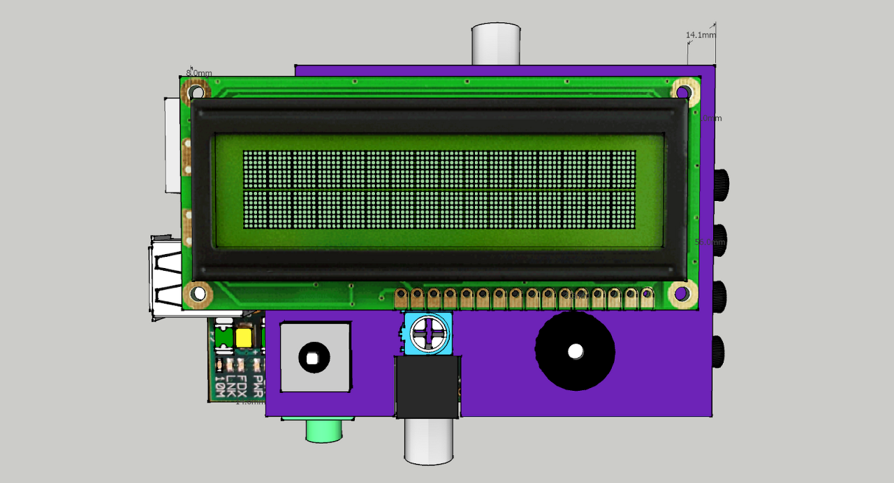
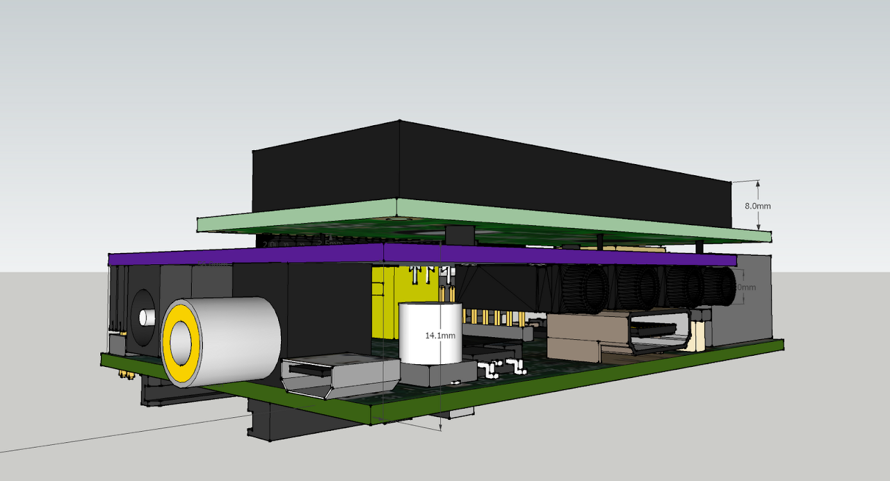
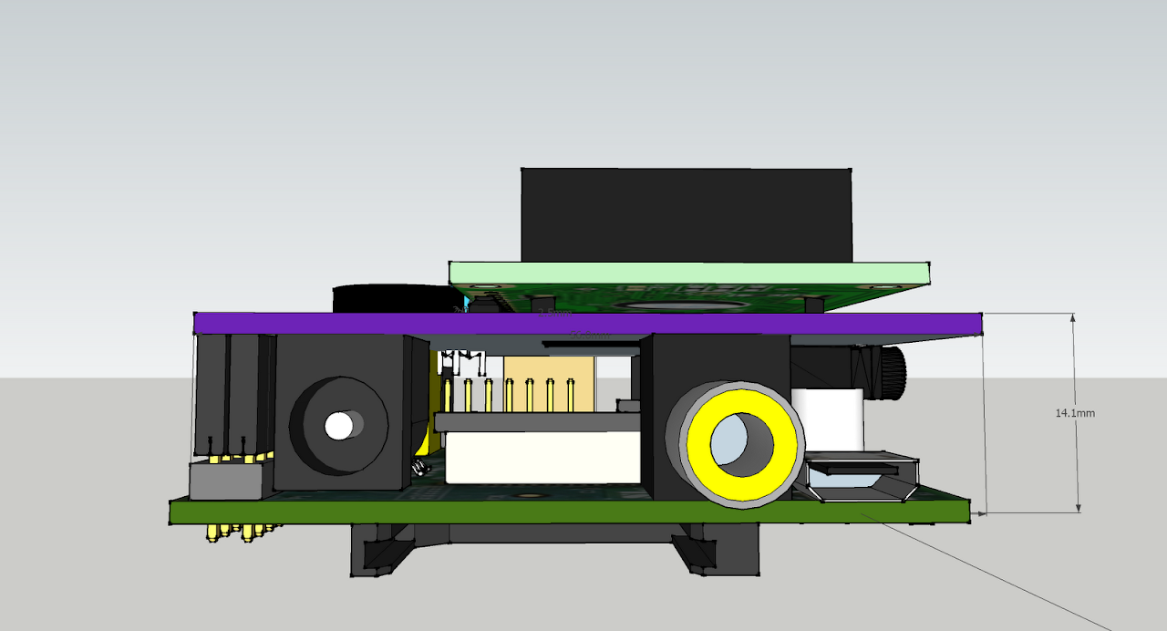
Whew. After spending all day redoing the layout I think I've got something I am happy with. The rules:
-- The board must be 4.1" wide, which is the same width as the Pi PCB and SD card measures.
-- The probe jacks must fit in a line
-- The LCD and button must be centered
-- The LEDs must be in a line and on an edge, facilitating the ability to have the stick up to the top of the finished device, or bent 90 degrees to stick out through the side of the device.
-- The Pi expansion header is in a fixed place.
-- All capacitors polarized in the same direction.
-- The Pi connector keepout areas, oh god the keepout areas. This was by far the hardest part of this project, keeping components out of the areas where the RCA and headphone jacks are on the Pi.
Looks like this now, 20mil power traces, 12mil signal traces, only 3 vias! I still have to do the silkscreen but I think that will wait for tomorrow, I've been working on this for 11 hours just today.


