Probe 3 inop


IvanTrail

TVWBB Member
I got my Heatermeter V4.3 with Raspberry Pi Zero W up and running for the most part.
However, probe 3 reads constant 265V with or without a probe inserted.
The other two work just fine, as does the thermocouple.

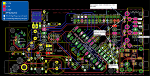
I will attach a picture indicating the checks I did and the results. In addition the continuity checks good to the AVR chip leg.

I am prone to using voltage drops where I can as a habit from electrical diag on cars, but I was having a heck of a time accessing both sides of the board while powered. So continuity checks were done in their stead.

Any ideas or suggestions on other checks to perform are greatly appreciated.
 

Attachments

  • Heatermeater diag.png
    Heatermeater diag.png
    642.7 KB · Views: 7
There's not much circuit there for the probes, just the jack, the 10K pullup resistor and the RC filter (resistor and cap) and the ATMega. Have you verified the 3.3v is getting to the 10K pullup for probe3?
 
There's not much circuit there for the probes, just the jack, the 10K pullup resistor and the RC filter (resistor and cap) and the ATMega. Have you verified the 3.3v is getting to the 10K pullup for probe3?
Where does the 3.3V source come from? I couldn't deduce that from the diagram and I am not an electronics guru. As far as I can tell the jacks are all fed through the same leg and the return splits for each through the 10K and the filter for each measurement. So, I should check the jack side of the resistor for 3.3V compared to ground. Is that correct?
 
Yeah it splits off going/coming from the 3.3V pin on the probe pinheader to each 10k resistor. With no probe plugged in it should read 3.3V on both sides of the 10k resistor, the voltage should drop on the furthest pin of the 10k resistor when a probe is inserted. The other should remain 3.3V.

To make troubleshooting easier, you can test without the LCD/Button board fitted-- it doesn't need to be connected at all for the HeaterMeter to run properly. Same thing with the Pi not being attached. Usually best to debug it without these just in case one of the two is somehow influencing the results.
 
Edit from before:

Thanks for the hint.

I checked and thought the resistor was bad, so I replaced it. Still no joy.

I see 3.3V to ground on the power side and 0.62V on the other side which tells me there is current flow through it, and that would indicate a partial short to ground after or through (?) the resistor... I think. It's been a minute since I did all this electrical diag!
 
Last edited:
Well, more mystery to add to the situation.

Briefly, probe 3 started working after replacing the resistor.
But, I got "No Pit Probe" even though the thermocouple was attached.
Checked the config, and everything went back to defaults.
When I changed back to the thermocouple, the set point was changed to 2.XXXXXX (don't remember the rest) mV instead of 5 mV.
Changed that and the pit probe was working again.
All probes were working. However, probe 3 would say -17 instead of not showing on the list when disconnected.
Then....

The processor on the Pi Zero W let the smoke out burning the tip of my finger in the process. This may well be what happened to the first one I posted about here: Clicky
And just fyi, it's the finger I use most to communicate with other people when driving! LOL

I have one more Pi, so I will flash it with snapshot.
Then check all the GPIO pins on the main board for correct voltage.

Thanks Bryan and Paul for the support.
 
Yeah there's something seriously wonky there, but I am not sure even what direction to point you. Usually when something is shorting on the 3.3V line, it takes everything down with it (you'll read like 2.2V across all the 3.3V points). Sorry I can't be more help but that's a really bizarre problem and I've got no followup, but you're right that something is pulling current between the far side of the 10k resistor and GND, but weirdly not enough to take it all the way down, which would just be 0.33mA. It is pulling just 0.268mA or possibly something else is also sourcing current into the mix from the other side. I am really just baffled.
 
It's got me baffled too.
I checked the voltage across the cap in that circuit and get 1.62V under power. From my circuits class in college, it seems that caps should act like an open circuit when charged, thereby making that a 3.3V reading across the legs. The other two probes read 3.3V, which seems to support my theory.

If that cap is partially shorted, could that cause the Pi to short out and smoke? If not, then I am stumped on that, because I can't see any problem with stray voltage getting to the GPIO pins with only the main board connected and powered. I am a bit hesitant to try my last pi until I have another or figure out why they are smoking.

Again, thanks for the help. You are truly kind and tremendously appreciated.
 
Maybe you have a bunch of flux on the board? That can sometimes "kinda" short things out / drag things down. You can clean the board with some isopropyl alcohol (without power applied!) and a soft brush, let it dry thoroughly before you power on.
I would say generally inspect your solder work across the board, look for long component leads, solder balls etc. When I have an odd problem I generally do a quick solder reflow on broad areas of the board followed by a cleaning...
 
I would be really hesitant to put your last Pi on it too. Something is certainly weird and without figuring it out first, I think you're going to be doomed to repeat what happened last time.

If you want, you can send it to me to see if I can figure it out. I have a whole room full of equipment that might be of some use. I can't guarantee that I'll be able to figure it out, but I do have a lot of experience with them and it would only cost you shipping both ways and the cost of any parts I'd replace. Email me if you're interested heatermeter@capnbry.net.
 
Here are a couple pictures for your viewing leisure.

Bryan, I certainly appreciate the offer. I have a few caps coming in the mail and will replace the suspect one when it gets here. If that doesn't work, I will certainly reach out to you.
 

Attachments

  • PXL_20201028_213528969.jpg
    PXL_20201028_213528969.jpg
    265.1 KB · Views: 12
  • PXL_20201028_213443594.jpg
    PXL_20201028_213443594.jpg
    230.5 KB · Views: 10
Well, I replaced the cap and the voltages seem to go where they should. Probe 3 still occasionally flashes some weird numbers every couple minutes but I suspect it's because they are just some probes I had from an old no name thermometer.

The Pi board doesn't get even remotely hot. So I hope that is all working out now.

I think we can put a fork in this one.

Moral of the story: It might be a dud capacitor that causes high probe readings.
 
Wow that's certainly weird. Was it one of the 0.1uF yellow capacitors? I'm not even sure how that would affect the Pi considering from the probe to the ATmega is somewhat isolated by the 10k and 100k resistors.

Super to hear you found a solution but it really still has me scratching my head.
 
Yes, one of the 0.1uF at the "Filter" for probe 3.

I don't know why my Pi kept smoking. I don't see how that cap could have made any of the GPIO pins short or over volt. I honestly don't think it was that.

I don't know if the flaky sd card could cause the processor to wig out and fry it. I do know that sd card would make the whole thing reset every power cycle, meaning I had to reconfigure everything in the web app. So I am guessing it might have made the AVR chip do funny stuff and possibly mess up the cap. Possibly a high frequency back feed from the AVR? I don't know enough about caps to know if rapid charge and discharge could cause a failure. (I know car batteries don't like it)

Anyway, I am just happy it's working now. I really enjoy making projects like this. Especially when it involves making good BBQ as the final result!


Back
Top