I finally have heatermeter in use, and did my first cook yesterday, after more than 2.5 months of trying to get a heatermeter! While it was not without challenges either, I am sure I will be able to work those out with some adjustments. The goal is very close now. ")

So, after spending something like 10 hours on finding and ordering stuff from various places (digikey, mouser, ebay, OSH Park), as I couldn't order directly from Heatermeter Store at the time I got started with this project as the store was closed due to COVID-19, I eventually had all the parts and boards in hand. I learned the hard way (spending another 10 hours trying to solder and test) that SMD soldering is not something I can do, nor is it something I want to do in the future either - it's a skill I have had very little need for until now, and I expect to be able to outsource any needs I might have in the future. I was right in my initial thoughts, that a kit with the SMD part done would have been the right option for me. Anyway, as I had tried and failed to build the SMD part of the heatermeter board, and having spent 2.5months on all this in total, I didn't want to wait until the whole BBQ season is over. So, Friday last week I ordered a fully assembled heatermeter 4.3 with thermocouple from the Heatermeter Store with expedited shipping. It was delivered on Thursday this week, so you can really call it expedited - 6 days from Florida to Finland.
So, I put it together, followed Bryan's very clear instructions and installed the Heatermeter on the Pi Zero W, started it up and plugged in the damper I had built. It worked right away! With the clear instructions I was able to quickly adjust the servo so that it opens and closes fully, as intended. And then yesterday on my day off I decided to make some meaty ribs. Got them out of the ribs and went to start up the grill with the heatermeter. Set the desired temp to 110C (the UI on the heatermeter unit is very clear and simple & intuitive to use!) and let it burn with the top vent fully open. That might have been my initial problem, but the temperature shot over, to around 135C and as by then the damper had been fully closed for 15min, the fire had died. Rinse and repeat a couple of times, I fired it up again, this time adjusted the top vent to open just a crack, set it to automatic, it shot over, died...

I found this post https://tvwbb.com/threads/hm-keeps-...fire-dies-and-needs-to-be-relit-at-225.67779/ and adjusted the PID values to those same values, as the Kamander I have is very similar to Akorn. After the next re-fire, when it shot over to 130C again, I then just adjusted the temp up to 135C and this way it didn't kill the fire but rather started maintaining it quite nicely. Honestly this was my last resort, as I had promised my kids to take them for a ride in the convertible to get some ice cream, and I was 2.5h in instead of the 1h I told them, so I was on borrowed time already. Luckily it worked, and the ribs were cooking all the while we were out, although in a bit higher temperature than I would have wanted.
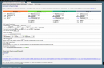
These are my PID settings now:

Can anyone point out what would be the best way for me to adjust, as based on my earlier experience with my grill without heatermeter, once the temperature drops by ~5C, you should be blowing all the air in that you can, so that you can get the fire going again, and then once you see the temp increase by more than a degree, you should stop blowing and quite quickly adjust the damper valve in order not to have it overshoot. I would also like heatermeter to take the overshoot into account when heating up - it should stop blowing at least 20C before the desired temperature, and start to close the damper so that when the target temperature is reached, it should only be something like 15-20% open to maintain that temperature.
Oh yeah, someone might be wondering why there's no meat probe. That's because I wanted to test the thermistor probes that I had, if those could be used. I didn't get a sensible response from any of those when testing with different preset coefficients, so I bit the bullet and ordered some thermoworks probes, looking forward to getting them next week. I am not fully confident on my chinese thermocouple either, but when I get the thermoworks probes, I will be able to check whether they show similar temps for the pit. I "calibrated" the pit TC to 100C with boiling water, but I am uncertain if it's really trustworthy and linear above 100C.
So, after spending something like 10 hours on finding and ordering stuff from various places (digikey, mouser, ebay, OSH Park), as I couldn't order directly from Heatermeter Store at the time I got started with this project as the store was closed due to COVID-19, I eventually had all the parts and boards in hand. I learned the hard way (spending another 10 hours trying to solder and test) that SMD soldering is not something I can do, nor is it something I want to do in the future either - it's a skill I have had very little need for until now, and I expect to be able to outsource any needs I might have in the future. I was right in my initial thoughts, that a kit with the SMD part done would have been the right option for me. Anyway, as I had tried and failed to build the SMD part of the heatermeter board, and having spent 2.5months on all this in total, I didn't want to wait until the whole BBQ season is over. So, Friday last week I ordered a fully assembled heatermeter 4.3 with thermocouple from the Heatermeter Store with expedited shipping. It was delivered on Thursday this week, so you can really call it expedited - 6 days from Florida to Finland.
So, I put it together, followed Bryan's very clear instructions and installed the Heatermeter on the Pi Zero W, started it up and plugged in the damper I had built. It worked right away! With the clear instructions I was able to quickly adjust the servo so that it opens and closes fully, as intended. And then yesterday on my day off I decided to make some meaty ribs. Got them out of the ribs and went to start up the grill with the heatermeter. Set the desired temp to 110C (the UI on the heatermeter unit is very clear and simple & intuitive to use!) and let it burn with the top vent fully open. That might have been my initial problem, but the temperature shot over, to around 135C and as by then the damper had been fully closed for 15min, the fire had died. Rinse and repeat a couple of times, I fired it up again, this time adjusted the top vent to open just a crack, set it to automatic, it shot over, died...
I found this post https://tvwbb.com/threads/hm-keeps-...fire-dies-and-needs-to-be-relit-at-225.67779/ and adjusted the PID values to those same values, as the Kamander I have is very similar to Akorn. After the next re-fire, when it shot over to 130C again, I then just adjusted the temp up to 135C and this way it didn't kill the fire but rather started maintaining it quite nicely. Honestly this was my last resort, as I had promised my kids to take them for a ride in the convertible to get some ice cream, and I was 2.5h in instead of the 1h I told them, so I was on borrowed time already.
Luckily it worked, and the ribs were cooking all the while we were out, although in a bit higher temperature than I would have wanted.These are my PID settings now:
Can anyone point out what would be the best way for me to adjust, as based on my earlier experience with my grill without heatermeter, once the temperature drops by ~5C, you should be blowing all the air in that you can, so that you can get the fire going again, and then once you see the temp increase by more than a degree, you should stop blowing and quite quickly adjust the damper valve in order not to have it overshoot. I would also like heatermeter to take the overshoot into account when heating up - it should stop blowing at least 20C before the desired temperature, and start to close the damper so that when the target temperature is reached, it should only be something like 15-20% open to maintain that temperature.
Oh yeah, someone might be wondering why there's no meat probe. That's because I wanted to test the thermistor probes that I had, if those could be used. I didn't get a sensible response from any of those when testing with different preset coefficients, so I bit the bullet and ordered some thermoworks probes, looking forward to getting them next week. I am not fully confident on my chinese thermocouple either, but when I get the thermoworks probes, I will be able to check whether they show similar temps for the pit. I "calibrated" the pit TC to 100C with boiling water, but I am uncertain if it's really trustworthy and linear above 100C.
Last edited: