Originally posted by D Peart:
<BLOCKQUOTE class="ip-ubbcode-quote"><div class="ip-ubbcode-quote-title">quote:</div><div class="ip-ubbcode-quote-content">Originally posted by Scott Miz:
Okay gang, been working on this project for a week; and alot of frustration is setting in.. Some of this I have no experience with so please help in the simpliest terms if you can...
Just to refresh, I have everything on my wrt54g assembled, including my linkmeter board, switch board and LCD board. My LCD works, and my button board works. I still dont have my probes or blower yet, but trying to make sure all is ready to go. I also can login wirelessly to the wrt54g homescreen; however everything is blank except for title " Current Pit". Then on my LCD display the temp starts out and just keeps climbing, I did post earlier and was told to put in temperature coefficients but I cant figure out how to do that. Please help me with the below things if you can.
1.) What I need to set in configuration page, and the easiest way of doing it.....
2.) Without temp probes installed, should I still get labeling, time and everything displayed regardless?? If not, what do I have to have set-up.
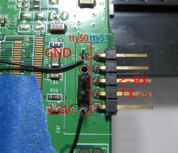
3.) How can I be totally sure my serial is working?? I used pins 2,4,6 & 10; however someone else recommended 1,3,5, & 9....
I have no programming knowledge, so please if anyone can provide help it would be greatly appreciated.... This is a great project and my BGE is just crying out for it, LOL; not to mention I am getting excited....
Thanks for any help....
Scott,
1. Did you hook up anything to the probes? I used the thermistor that came in the kit. Without setting any coefficients you will get a reading, it just wont be accurate. To test, just hook the thermistor to any of the probe pins and ground.
2. You should get labeling it should just show everything off. The graph should be updating as well. After you put the thermistor on the pit probe you will be able to see everything "working". But I think you issue in #3.
3. By default LM uses serial channel 1, I believe that this means you have to use 1,3,5 and 9. I've not seen an wrt54g yet that uses 2,4,6 and 10 for anything except serial0 which is the default terminal for the router. To know definitely you should look at your limkmeterd setup found in this post:
http://tvwbb.com/eve/forums/a/...261019426#4261019426
See the line:
option 'serial_device' '/dev/ttyS1'
That means you are using serial port 1. Double check you router specs, but I'm fairly confident you need to change your serial connection to 1,3,5 and 9.
dave </div></BLOCKQUOTE>
Dave and Bryan,
I think I got my serial communication worked out. It was that I originally hooked up the even pins on my linksys router, I switch to correct pins and started to work.....
Did have two follow-up questions that I want to be real clear on:
1.) Originally when I loaded flashed my wrt54g, I used the linkmeter firmware; however I did not load any hex files or anything else. Was this correct or do I need to load other stuff onto the router??????
2.) I still do not have my probes, but my understand is I use the thermistor to act as a probe; correct?? And if so, how exactly do I load the coefficients?? And do I have to do it for pit probe plus all probes individually????
Thanks for any continuing help......
Scott