LinkMeter v2 Homebrew BBQ Controller - Part 1


Status
Not open for further replies.
Now I am going to figure out how I can get openwrt with wireless and linkmeter on my WRT150N.

Bryan...I have learned more this weekend than in the 4 years since I got out of graduate school. Thanks for the education. My wife is a bit ****ed at me so I will have to put the project down for a couple days or risk certain death. I ordered 3 of your boards from Dorkbot. I don't have the parts for it yet so I need to figure that out since I don't think you have gotten to putting the parts list on wiki.

So I was able to flash the WRT150N with Openwrt Kamikaze (r18961). Wifi works and everything. It runs Luci v0.8.8. I did try to load the packages for linkmeter but it says they aren't compatible. What do I need to do to get linkmeter on my version of Openwrt?

If I can't get the linkmeter on the WRT150N, I will just have to find a WRT54GL on craigslist or something.
 
Bryan.....
I have been readin all the different thread on the heatermeter and the linkmeter. I have two questions. I am building a heatermeater with the wishield 2.0 and was wondering what had to be changed in the code to use a I2C LCD display. The second question is if I was to not include the wihield and wanted to use the I2C display what would need to be commented out? Thank you for all the great work and support that has been put into this project.

Duston
 
Originally posted by Dave S (GeoDave):
So I was able to flash the WRT150N with Openwrt Kamikaze (r18961). Wifi works and everything. It runs Luci v0.8.8. I did try to load the packages for linkmeter but it says they aren't compatible. What do I need to do to get linkmeter on my version of Openwrt?
I can't really say what it would take because I'm not sure what Kamikaze is built on, or what is different in LuCI 0.8 vs 0.10. I was hoping that Backfire 10.03 would be released by now because that's what release I was going to target for the "stable" linkmeter build. I am pretty sure there are a lot of serious changes between Kamikaze and Backfire 10.03 though, so packages built for one system won't run on another.
 
Originally posted by Duston Anthony:
I am building a heatermeater with the wishield 2.0 and was wondering what had to be changed in the code to use a I2C LCD display. The second question is if I was to not include the wihield and wanted to use the I2C display what would need to be commented out?
To use an I2C display, replace the ShiftRegLCD lcd class in hmcore.cpp with the I2C one and use those two digital lines as your I2C lines. You can not use the hardware I2C without moving the probes off those analog input lines as well.

The inclusion of WiShield is solely tied to defining HEATERMETER_NETWORKING at the top of hmcore.h. If that is defined you get WiShield support. Note that HEATERMETER_NETWORKING and HEATERMETER_RFM12 are somewhat mutually exclusive (one or the other).
 
Brian,
Does the board have the FTDI interface on it so that we can load the bootloader into the ATMega chip on the board, or will I need a different board for that?

thanks,
dave
 
Originally posted by D Peart:
Does the board have the FTDI interface on it so that we can load the bootloader into the ATMega chip on the board, or will I need a different board for that?
The v3.1 PCB that is in github has a spot for both an FTDI and ICSP header on it. However, you can't change bootloaders over the FTDI interface. You can program the bootloader over the ICSP interface, but it requires another Arduino that already has a bootloader on it, or a USBtinyISP or something.
 
OK I'll order the USBtinyISP not bad for $10.

For the serial connection to the router I see you have J8 on the HM board in the parts list. Does the parts list also contain the mating portion for the router or do I need to order that myself? I'd imagine that part would depend on the router being used, but thought I'd ask in case I was missing something.

thanks again,
dave
 
Originally posted by D Peart:
OK I'll order the USBtinyISP not bad for $10.

For the serial connection to the router I see you have J8 on the HM board in the parts list. Does the parts list also contain the mating portion for the router or do I need to order that myself? I'd imagine that part would depend on the router being used, but thought I'd ask in case I was missing something.
Oh I also forgot another alternative would be to buy it with Optiboot already on it, from Sparkfun or something. However, they don't say which version they install so there's no telling if it has the bugs that have been fixed by West. I'll try when I get home tonight to see if the v3.1 PCB works with the Arduino-0022 version of Optiboot (which I assume is what everyone puts on their "preloaded" avrs)

The parts list didn't list the mating part. Good catch! However, it is a male pinhd/90 so there's enough left over from the POW pin header to form the other half. I'll update the wiki to indicate that.
 
Got my order from Mouser for the parts for three boards.

Still need to order from Pololu and Digi-Key, just trying to get over paying more for shipping that the parts are worth.

I found the 1x5 and the female crimp pins from Pololu at Fry's, but did not find the 1x2s. Still looking around while I wait for the boards to show up.

dave
 
Originally posted by D Peart:
Still need to order from Pololu and Digi-Key, just trying to get over paying more for shipping that the parts are worth.
Even worse is that I think the cost of the interconnects is more than the cost of the actual parts used. All the pin headers and shrouds and crimp connectors are not only the hardest parts to find, but they're friggin expensive! One could build this thing a lot cheaper if everything was soldered directly to the board.

I wish there were Fry's down in Florida. That place sounds awesome.
 
I found that on certain components you can get muh better deals on eBay directly from China. Most LCDs are $11-15 if you buy them from the usual online retailers. You can get a nice 16x2 LCD in two weeks from China for $3 with free shipping. They are as good as the ones from Sparkfun/digikey/mouser. You can also buy headers cheaper too. I guess it depends on how you feel about ordering from China.
 
Originally posted by D Peart:
do you think these parts would work? You can order them from mouser instead of pololu. These do have a little locking mechanism to lock to the board connector.
Looking at the dimensions I don't see anything wrong, they're 0.1" spacing with 0.05" holes. The pin headers are 0.1" spacing and the pins are 0.04". I assume that's the right size. The connectors themselves are a little thicker on one side than the standard shrouds but if it is a problem you could just orient them the other way so the fat part is on the outside.

The interconnects are really "whatever you can find" because I have such a hard time locating suitable parts. I just listed what I used. Poulu's shipping isn't bad if you order like 1,000 pieces like I did.
 
Originally posted by Bryan Mayland:
<BLOCKQUOTE class="ip-ubbcode-quote"><div class="ip-ubbcode-quote-title">quote:</div><div class="ip-ubbcode-quote-content">Originally posted by D Peart:
do you think these parts would work? You can order them from mouser instead of pololu. These do have a little locking mechanism to lock to the board connector.
Looking at the dimensions I don't see anything wrong, they're 0.1" spacing with 0.05" holes. The pin headers are 0.1" spacing and the pins are 0.04". I assume that's the right size. The connectors themselves are a little thicker on one side than the standard shrouds but if it is a problem you could just orient them the other way so the fat part is on the outside.

The interconnects are really "whatever you can find" because I have such a hard time locating suitable parts. I just listed what I used. Poulu's shipping isn't bad if you order like 1,000 pieces like I did. </div></BLOCKQUOTE>

I'm going to get some samples and I'll post how they work.

dave
 
Originally posted by Bryan Mayland:
Continuing from the origianl LinkMeter thread to avoid confusion of "Research and Development" information.

LinkMeter is an OpenWrt firmware / package for interfacing to a HeaterMeter Arduino / ATmega328 based automatic BBQ controller. The fusion allows the HeaterMeter to control the grill temperature, while passing the heavy lifting of WiFi access and data storage off to the OpenWrt-compatible router. A more concise description can be found in An Introduction to LinkMeter & HeaterMeter

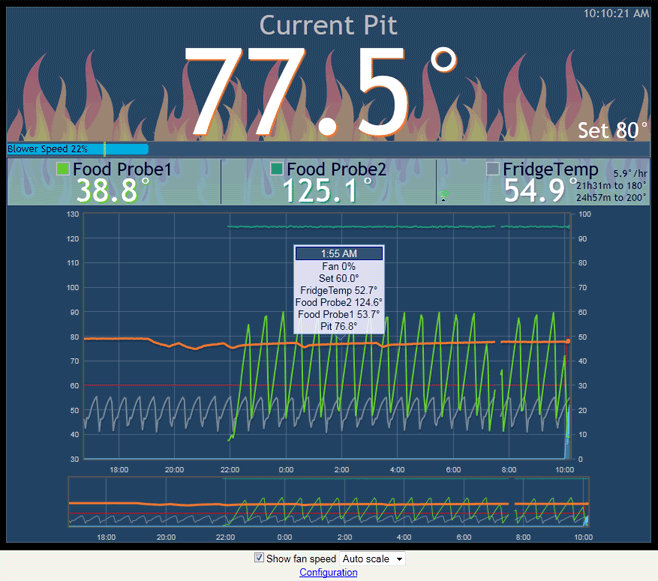
LinkMeter Home Screen
linkmeter-2011081001.png


Project Page - GitHub Hosting
LinkMeter is an open source project and is hosted on my GitHub page. The ultimate source for information is the Wiki which I will flesh out as we go.

Hardware
The official schematic is in GitHup as well, the EAGLE top level directory. A parts list is available in the Wiki.

Ed's Original LinkMeter


As you can tell the preferred platform is the Linksys WRT54GL router. A rough outline of the required steps to build a LinkMeter
1) Build a HeaterMeter-for-LinkMeter ATmega328 board. IMPORTANT while you can use the HeaterMeter design from the standalone HeaterMeter schematic posted in the other thread, the official schematic from GitHub has additional components to support additional functionality, as well as being designed to fit inside the WRT54GL case. The official new schematic can also be used in a standalone fashion.

2) Flash the HeaterMeter with the arduino/heatermeter firmware. This can be done with a USBtinyISP, another Arduino, or any other ICSP programmer you might have.

3) Flash your WRT54GL with a prebuilt LinkMeter firmware image. Snapshot recommended image. The packages are pre-installed and are only supplied for users wishing to install them on their own firmware.

4) Connect the HeaterMeter to your router via the internal serial port.

5) Plug your computer directly into one of the LAN ports. You will be assigned a network address (DHCP) in the 192.168.200.x range. Configure your wireless settings using the web interface at http://192.168.200.1/. Generally, you want your wireless to be configured in Client mode (aka station mode) on your existing wireless network and to use DHCP.

6) Configure your probes depending on your build and probe types. (More information here soon)

7) BBQ

GREAT WORK and such a wonderful topic line. I have been following these links very interested and just now decided to take the push to make one of my own. I hope you all can give me some expert advise, and bare with me for asking anything to dumb...

I got my hands on a WRT54G Ver 2, and I performed the openwrt to my router, and was able to log in via luci. I then ran the linkmeter-brcm47xx-squashfs.trx flash, at which time I had to log into 192.168.200.1; and I am viewing the current pit window.

I am not sure am I suppose to also flash the linkmeter-wrt54g-squashfs.bin ?? Or have I done things in the wrong steps?? I am just trying to get my router set-up awaiting all my components....

Like I stated before, I am running a WRT54G Ver 2, when I took it apart my board is not like many of the images; trying to figure out serial port???

Also, on schematic what are the below connectors for:
1.) J8 - FTDI
2.) J6 - ICSP ( i think it's serial port )
3.) P5 - RTR

and what do 4 buttons do on face of router.....

Sorry for all the questions, really feel like I am missing stuff.

Thanks

Thanks for any help
 
Originally posted by Scott Miz:
A -- I am not sure am I suppose to also flash the linkmeter-wrt54g-squashfs.bin ??

B -- Like I stated before, I am running a WRT54G Ver 2, when I took it apart my board is not like many of the images; trying to figure out serial port???

C -- Also, on schematic what are the below connectors for:
1.) J8 - FTDI
2.) J6 - ICSP ( i think it's serial port )
3.) P5 - RTR

D -- and what do 4 buttons do on face of router.....
A) The linkmeter-wrt54g-squashfs.bin is only needed if you have to flash from the recovery. The trx image is used if you flash from OpenWrt.

B) Yeah the non-L version doesn't have the nice board cutout on it. Your serial ports are the 2x5 header on the front right (looking from the front). Only 1x5 will be used (if it is like the -L, it will be pins 1-5).

C) J8 connects with an "FTDI" cable, which is a somewhat standard way to connect Arduinos to PCs. J6 is where you can flash the chip bootloader with an ICSP programmer. If you don't have an ICSP programmer, you'll need an ATmega with the bootloader pre-installed. P5 is the actual connection to the router, which is 3.3V TTL serial. The router is the only one you'll need to use if you have a bootloader.

D) You can directly control the unit without using the wireless by using the menu system and buttons on the front. See the HeaterMeter docs in the wiki for more info on that.
 
Originally posted by D Peart:
OK I got your brd, and sch files from github this AM. Look like they were updated yesterday.

I then used your cam file to create the ger and gpi files. I got the following:

bottomlayer
tcream
toplayer
boardoutling
bottomsilkscreen
bottomsoldermask
drills
topsilkscreen
topsoldermask

I got a .ger and .gpi for all except drills which gave me dri and xln.

I tried to run the cam file from the dorkbot website but it didn't work for me. From what I listed above does it look correct?

thanks,
dave

Hey Dave, How did you do all this above, just trying to learn
 
Download Eagle from here:

http://www.cadsoftusa.com/downloads/

Download the cam file from this post:
http://tvwbb.com/eve/forums/a/...411059526#5411059526

Download the brd, sch files from here:

https://github.com/CapnBry/Hea...er/tree/master/eagle

Install eagle,

load the brd file into eagle.

file->CAM Processor
file->open->Job
select the cam job you downloaded

Then Process Job

It will write all the files out, then you can submit them to Dorkbot for fabrication. If you are going to a different place for the boards, there will be a different cam file to run.

hope this helps,
dave
 
Bryan,

Do you have an example of the transmitter side of the RFM12B radio?

Curious if you've looked into this.

thanks,
dave
 
Status
Not open for further replies.


Back
Top