LinkMeter v2 Homebrew BBQ Controller - Part 1


Status
Not open for further replies.
Bryan,

Since I am currently building the stand-alone version I used the "HeaterMeter software step by step (Windows)" under "Installation of HeaterMeter" in the Wiki. I just uploaded the AVR firmware via the Arduino software, and an Arduino Uno board, with the code provided on the wiki. The hex file would be used to flash the AVR via the web interface (router) right? Since I don't have a working router at the moment, this option isn't available to me so I haven't used any hex files. Hope this helps...

-Edwin

Originally posted by Bryan Mayland:
<BLOCKQUOTE class="ip-ubbcode-quote"><div class="ip-ubbcode-quote-title">quote:</div><div class="ip-ubbcode-quote-content">Originally posted by Edwin Gonzalez:
So I received the boards (V3.2) on Saturday and immediately soldered on the components. I fired the Heatermeter up and I got the "square blocks of death" on the screen. I read through all the postings and apparently this seems to be a common problem. I began troubleshooting/debugging and found no errors. I have done the following:
Oh noeeees! This was what v3.2 was supposed to be all about: not having those.

-- Which hex file did you flash, or did you build your own
-- Also I assume your shift register is a 74HC595N (not 74LS164) right? I would think that would be obvious though, as they have different pin counts.
-- Have you tried adjusting the contrast pot? All the way in one direction should make all the boxes go away. That also checks the orientation of the LCD (if it is flipped around it wouldn't do anything)
-- EDIT: Also check the orientation of the 74NC595N, it should have the notch facing the left (with the LCD header toward you) </div></BLOCKQUOTE>
 
So? How did it turn out?

dave

Originally posted by Joe Loyd:
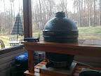
Finally, sitting back with a margarita in one hand and the prime in the other and watching my first Linkmeter controlled test smoke! Thanks to Bryan and D Peart for all the help getting this up and running!

IMG_20120317_173524.jpg
 
Originally posted by Edwin Gonzalez:
Since I am currently building the stand-alone version I used the "HeaterMeter software step by step (Windows)" under "Installation of HeaterMeter" in the Wiki. I just uploaded the AVR firmware via the Arduino software, and an Arduino Uno board, with the code provided on the wiki. The hex file would be used to flash the AVR via the web interface (router) right? Since I don't have a working router at the moment, this option isn't available to me so I haven't used any hex files. Hope this helps...
Ah yes. If you just built it using the Arduino IDE using the code from at least mid-February, the code is the right version. The Arduino IDE actually builds a hex file then handles the upload for you.

If you want to try a software fix, check in the (heatermeter project)/arduino/libraries/ShiftRegLCD/ShiftRegLCD.cpp and go to line 307 and uncomment the spi_byte line here:
<pre class="ip-ubbcode-code-pre">

void ShiftRegLCDSPI::spi_lcd(uint8_t value) const
{
// The datasheet says that RS needs to be set-up 60ns before E goes
// high but in my testing this caused the display to get wrecked
//spi_byte(value);
</pre>
And rebuild and reupload it. If it doesn't work you're going to want to switch it back because it caused my LCD to sometimes fail initialization and always get messed up over time.
 
Originally posted by Bryan Mayland:
<BLOCKQUOTE class="ip-ubbcode-quote"><div class="ip-ubbcode-quote-title">quote:</div><div class="ip-ubbcode-quote-content">Originally posted by Ben Lawson:
And this is the atmega I got from sparkfun, ATmega328 with Arduino Optiboot (Uno)
It is odd it doesn't look like it has either bootloader on it, or the serial isn't working correctly.

If you check at the ATmega while it is plugged into the serial port, you should have:
Pin 1 (RESET): 5V
Pin 2 (RX): 3.3V
Pin 3 (TX): 5V

When you hold down the reset button, pin 1 should go to 0V. If you check at the router connection, the pins should have (starting from the pin closest to you) 3.3V, 3.3V, 3.3V, (don't care), 0V.

If that all checks out then either the router's serial port isn't working, or the chip has no bootloader. You can try testing the serial port by removing the HeaterMeter board and jumpering the RX and TX pins together and opening 2 terminal connections to the router. In the first type
/etc/init.d/lucid stop
cat /dev/ttyS1

In the second type
echo TEST > /dev/ttyS1

And you should see "TEST" appear in the first terminal. </div></BLOCKQUOTE>

Man, I am having the worst luck with this....

I have 2 wrt54gl's to test with. The first one I was working with wasnt getting the correct readings on the serial port, RX and TX were really low.

So i soldered up the pin header and 12v lead to the second router.

Voltage was good on router 2, 3.3,3.3,3.3 before plugging the linkmeter board in.

I plugged in the linkmeter, everything seemed ok, I started testing the pins on the atemega. I got:
Pin1 5v
Pin2 3.3v
Pin3 .5ish, really low

So then I started to check the serial pins on the router again, and SNAP!. I'm not sure what happened. I think maybe my 12v touched something on the router it shouldn't have, or i bridged some pins with my multimeter.

Luckily the router still works, but now I am getting 3.3v, 1.25v, 1.25v at the serial port. I guess its fried? ugh...just my luck....
 
Originally posted by Ben Lawson:
I plugged in the linkmeter, everything seemed ok, I started testing the pins on the atemega. I got:
Pin1 5v
Pin2 3.3v
Pin3 .5ish, really low

Luckily the router still works, but now I am getting 3.3v, 1.25v, 1.25v at the serial port. I guess its fried? ugh...just my luck....
Yeah something is definitely wrong if your pin 3 is that low. It should read 5V at the chip and every 2 seconds it should dip a little (as when HeaterMeter transmits it goes to 0V for a fraction of a second). You can hook up 12V/ground to the power connector (without hooking the router interface up) and see what you get there.

It does sound like you zapped your serial port. The ttyS0 might still be good though! Test the other set of pins with your multimeter and see if they're good. If so, you can just clip the RX/TX pins of the router pinheader and jump ttyS0 over to it. My router runs like this because I too have touched the multimeter to 12V and fried my ttyS1. It requires a couple of the router's files to be modified but it is easy, and if your ttyS0 is working then I can tell you how.

Check the board out by itself though first, because if you're not seeing 5V on pin 3 you need to fix that first.
 
Doing a test run with a boston butt today and my new LinkMeter. I'm pretty excited. Thanks Bryan and everyone else for your help. Everything seems to be going good except for the graph. All of the probe temps and fan speed show up on the LinkMeter home page, but the graph area just has the progress bar scrolling. I tested this setup in the house multiple times and it worked great. The LinkMeter has good signal outside. I was able to get the graph for a short while and it looked fine, but when i tried to change the scale it seems to be having trouble updating. Has anyone else experienced this? Thanks
 
As advertised! I was was surprised at how well it's is able to track and maintain a stable temp... Now, if it could only proactively cool it down when it gets too hot...maybe a wireless servo on the top vent....

Originally posted by D Peart:
So? How did it turn out?

dave

<BLOCKQUOTE class="ip-ubbcode-quote"><div class="ip-ubbcode-quote-title">quote:</div><div class="ip-ubbcode-quote-content">Originally posted by Joe Loyd:
Finally, sitting back with a margarita in one hand and the prime in the other and watching my first Linkmeter controlled test smoke! Thanks to Bryan and D Peart for all the help getting this up and running!

IMG_20120317_173524.jpg
</div></BLOCKQUOTE>
 
Originally posted by Joe Loyd:
As advertised! I was was surprised at how well it's is able to track and maintain a stable temp... Now, if it could only proactively cool it down when it gets too hot...maybe a small servo on the top vent....

<BLOCKQUOTE class="ip-ubbcode-quote"><div class="ip-ubbcode-quote-title">quote:</div><div class="ip-ubbcode-quote-content">Originally posted by D Peart:
So? How did it turn out?

dave

<BLOCKQUOTE class="ip-ubbcode-quote"><div class="ip-ubbcode-quote-title">quote:</div><div class="ip-ubbcode-quote-content">Originally posted by Joe Loyd:
Finally, sitting back with a margarita in one hand and the prime in the other and watching my first Linkmeter controlled test smoke! Thanks to Bryan and D Peart for all the help getting this up and running!

IMG_20120317_173524.jpg
</div></BLOCKQUOTE> </div></BLOCKQUOTE>
 
Originally posted by Bryan Mayland:

Yeah something is definitely wrong if your pin 3 is that low. It should read 5V at the chip and every 2 seconds it should dip a little (as when HeaterMeter transmits it goes to 0V for a fraction of a second). You can hook up 12V/ground to the power connector (without hooking the router interface up) and see what you get there.

It does sound like you zapped your serial port. The ttyS0 might still be good though! Test the other set of pins with your multimeter and see if they're good. If so, you can just clip the RX/TX pins of the router pinheader and jump ttyS0 over to it. My router runs like this because I too have touched the multimeter to 12V and fried my ttyS1. It requires a couple of the router's files to be modified but it is easy, and if your ttyS0 is working then I can tell you how.

Check the board out by itself though first, because if you're not seeing 5V on pin 3 you need to fix that first.

I hooked the 12v barrel jack connector up, without the router interface.

Barrel Jack gets something like 16v

Barrel Jack GND to Pin1 Atmega gets 4.96v
Barrel Jack GND to Pin2 gets .3v
Barrel Jack GND to Pin3 gets 0v

I fried the original atmega that was in it, it was messing with the resistance in R2 and R21. I replaced R2 and R21 and had the same issue so I replaced the Atmega and R2 and 21 started getting the correct ohms readings again.

I went back through and touched up some solder connections but it didnt make any difference.

I also picked up a Arduino Uno so I could be sure I have a good bootloader on it. When I try to Burn the bootloader, I get an error from avrdude saying the same thing about not being in sync.

Since I got the Uno, I need to put a 10uf cap between Reset and GND, I did that on the backside of the Linkmeter board behind the ICSP header, is that the correct place?

I guess my next step is to pull the current atmega from the linkmeter board and wire it up directly to the Uno and see if it can burn the bootloader.

I'm losing my mind!!!
 
I was wrong about getting the same error when trying t flash the bootloader using the Uno, I had the serial port configured wrong.

Here is the real error that I get now when trying to burn the bootloader:

avrdude: stk500_program_enable(): protocol error, expect=0x14, resp=0x50
avrdude: initialization failed, rc=-1
Double check connections and try again, or use -F to override
this check.


I've double checked my connections between the linkmeter and the Uno and they all seem right to me.

I tried -F but, it just threw more errors
 
Hi,

I'm just starting out on the challenge of building my own Linkmeter...

Being based in the UK, I have a few additional challenges sourcing the same components without having to order directly from US suppliers and face paying for shipment and UK import charges.

I'm doing ok in finding most components locally... once I have my completed my parts list I'll post here to ask for the collective 'group' to check for errors!

I was wondering if anyone has a v3.2 PCB 'spare' which they would be willing to sell me...

Thanks

Nick
 
Originally posted by Ben Lawson:
Since I got the Uno, I need to put a 10uf cap between Reset and GND, I did that on the backside of the Linkmeter board behind the ICSP header, is that the correct place?
The RESET prevent cap goes on the Uno, not the HeaterMeter.

Since you've got an Uno now, I'd suggest using the Optiloader method from the wiki to guarantee you've got Optiloader on the target chip. There are no additional components needed, just the 6 wires detailed in the steps.

Once it has the bootloader, you can put the HeaterMeter chip in your Uno shield and upload the HeaterMeter code directly from the IDE. Because you have a v3.1 board make sure to uncomment the #define SHIFTREGLCD_NATIVE in hmcore.h (remove the two leading //) before you upload.
 
Bryan,

I'm eager to build my first LinkMeter, although at this point I think I'm going to wait for the Raspberry Pi version rather than trying to acquire a Linksys Router (I have a Raspberry Pi coming, at least once they figure out these delays)

I am wondering if you've considered a simple feature addition, though. While my primary goal would be smoking meat, it seems like the controller could be easily adapted for related uses.

For example, I would love to try sous vide cooking a steak and others would probably be interested in beer brewing or precise fridge control.

Since the controller already has the temperature measurement and interfaces done, it seems like it wouldn't be much of a stretch to add this.

I'm wondering if it would difficult for you to just add basically another output to the PCB, so instead of just controlling the voltage of the blower it could also be used as an external switch, and then something like the PowerSwitch Tail could be connected so the controller could switch an outlet on or off (or someone could build their own relay controller of course).

Then when not smoking we could just connect it to a rice cooker or crock pot and make some perfect, cheap, steak!

I would be able to contribute on the software side if desired.

Thanks for this project!
 
Originally posted by NickH:
I'm wondering if it would difficult for you to just add basically another output to the PCB, so instead of just controlling the voltage of the blower it could also be used as an external switch, and then something like the PowerSwitch Tail could be connected so the controller could switch an outlet on or off (or someone could build their own relay controller of course).
Set MIN_FAN_SPEED to 100 in grillpid.cpp and cachaw! the controller will only turn on and off. The switch will operate 12V and will drive an inductive load like a relay. If you only want 5V, you can not populate the MOSFET and use the gate input (pin 1) of its placement. I wouldn't drive a relay with that though because of the feedback when it clicks on and off.

There isn't any built-in hysteresis though so there's a possibility of turning on/off at 2sec intervals if the probe temperature is riding the transition.
 
Originally posted by Bryan Mayland:
Set MIN_FAN_SPEED to 100 in grillpid.cpp and cachaw! the controller will only turn on and off. The switch will operate 12V and will drive an inductive load like a relay. If you only want 5V, you can not populate the MOSFET and use the gate input (pin 1) of its placement. I wouldn't drive a relay with that though because of the feedback when it clicks on and off.

There isn't any built-in hysteresis though so there's a possibility of turning on/off at 2sec intervals if the probe temperature is riding the transition.

Ahh, interesting...I will have to try this after I build the controller. Well, after I smoke some meat, that is the first priority :)
 
Originally posted by NickH:
Ahh, interesting...I will have to try this after I build the controller. Well, after I smoke some meat, that is the first priority :)
Yeah, theoretically it should work. I've never tried it. One issue is that the controller will work in 10 second periods, running at 100% for [desired speed] / 10 seconds. For example, if HeaterMeter wants to apply 40% power, it will apply 100% for 4 seconds then 0% for 6 seconds, and repeat.

This sounds like it would be the proper way to control it but many relays have a rated life on the order of 100,000 switches. 100,000 switches x 10 seconds = only 11.5 days of total runtime before you should start expecting it to fail. I'm not sure how normal on-off type controllers work around that.
 
Originally posted by Bryan Mayland:
Yeah, theoretically it should work. I've never tried it. One issue is that the controller will work in 10 second periods, running at 100% for [desired speed] / 10 seconds. For example, if HeaterMeter wants to apply 40% power, it will apply 100% for 4 seconds then 0% for 6 seconds, and repeat.

This sounds like it would be the proper way to control it but many relays have a rated life on the order of 100,000 switches. 100,000 switches x 10 seconds = only 11.5 days of total runtime before you should start expecting it to fail. I'm not sure how normal on-off type controllers work around that.

Yes, couldn't I just change the period in GrillPid::commitFanSpeed? It looks like right now it is hardcoded with 10,000 ms, but I imagine for this application, since there would be probably more than a gallon of water as thermal mass, that this quick of cycling would probably be overkill. I would just need to do some more testing, though. I would need to read more about it, but its also possible that the controllers commonly use solid-state relays. Then you don't really need to worry about the switch time. Certain loads wouldn't work, but for this application its just a resistive heater, and then of course you also need to spec the SSR to make sure it handles enough amps.
 
Originally posted by NickH:
Yes, couldn't I just change the period in GrillPid::commitFanSpeed? It looks like right now it is hardcoded with 10,000 ms
You could, but I'd say that doesn't really fix the problem, it just makes it work a little longer. You'd probably want want to figure out what sort of algorithm commercial controllers use and then adapt that. It might just be the same sort of thing HeaterMeter would do, but I wouldn't say "HeaterMeter can do sous vide as well!" without exploring better how to prevent it from failing down the road.
 
Originally posted by Bryan Mayland:
You could, but I'd say that doesn't really fix the problem, it just makes it work a little longer. You'd probably want want to figure out what sort of algorithm commercial controllers use and then adapt that. It might just be the same sort of thing HeaterMeter would do, but I wouldn't say "HeaterMeter can do sous vide as well!" without exploring better how to prevent it from failing down the road.

OK, thanks Bryan, I will look into this more once I have a HeaterMeter built, but at least I have a starting place and I think the hardware should work.
 
Originally posted by N Waring:
Hi,

I'm just starting out on the challenge of building my own Linkmeter...

Being based in the UK, I have a few additional challenges sourcing the same components without having to order directly from US suppliers and face paying for shipment and UK import charges.

I'm doing ok in finding most components locally... once I have my completed my parts list I'll post here to ask for the collective 'group' to check for errors!

I was wondering if anyone has a v3.2 PCB 'spare' which they would be willing to sell me...

Thanks

Nick

I've got a spare, shot me your addy to griffbosun at gmail dot com. Dave
 
Status
Not open for further replies.


Back
Top