LinkMeter v2 Homebrew BBQ Controller - Part 1


Status
Not open for further replies.
Originally posted by Bryan Mayland:
The alarm system is going to have hooks for calling scripts which could then do whatever you want, such as send an email, send an android notification message, post to facebook, whatever you like.

Sounds awesome!
 
Originally posted by Arwin:
My first controller doesn't have an lcd or network at all so it only has some leds. I found out that it's usefull to have "temp ok" and "food ok". It gives me the possibility to check from a distance if everything goes well. The food ok led goes on when the food-temp reaches the desired setpoint and temp ok is just like you mentioned within x% of setpoint.

I would second this. If I know the temp is OK, I don't care if the fan is running or not, and having the food LED is kind of a simple alarm. I don't always hook up my linkmeter and having the two indicator LEDs would be awesome. Would you be willing to upgrade the v3.1 firmware to support this? I'll just blue wire in the LEDs.

dave
 
Bryan,

Just tested it out, here is what I get:

root@OpenWrt:/# lmclient LMDC,0
nil poll
root@OpenWrt:/# lmclient LMDC,1
nil poll

That didn't do anything.

root@OpenWrt:/# /etc/init.d/lucid restart
Stopping LuCId superserver: lucid.
Starting LuCId superserver: lucid.

Worked just fine.

dave

Originally posted by Bryan Mayland:
<BLOCKQUOTE class="ip-ubbcode-quote"><div class="ip-ubbcode-quote-title">quote:</div><div class="ip-ubbcode-quote-content">Originally posted by D Peart:
I have restarted the HM, but that doesn't fix it, so it has to be an LM issue. I'll try restarting the webserver, need to go figure out how to do that again, and see if that fixes it. I do know a reboot of LM gets it up and working again, at least temporarily.
When it breaks try
lmclient LMDC,0
lmclient LMDC,1

That restarts the serial reader/writer process of the daemon first. Then try to see if you can change things. If not then the fallback is
/etc/init.d/lucid restart

There's already a diode between the 12V input and the 5V regulator. The fan power is tapped from before the diode, and there's 47uF capacitor after the diode, so it was my thinking that this should help protect the AVR device from getting "browned out". Apparently not though. You might also try putting your big capacitor not in the standard spot, but rather with the positive capacitor lead in the hole where the negative lead is supposed to go, then put the negative lead to ground. I've seen capacitors hooked this way to motors in some datasheets. </div></BLOCKQUOTE>
 
Originally posted by D Peart:
I would second this. If I know the temp is OK, I don't care if the fan is running or not, and having the food LED is kind of a simple alarm. I don't always hook up my linkmeter and having the two indicator LEDs would be awesome. Would you be willing to upgrade the v3.1 firmware to support this? I'll just blue wire in the LEDs.
Yeah I was just going to make it a function of the LCD class. With the v3.1 boards, the LEDs will dim as the LCD is updated though.

I'd like to think about it and have some more ideas for what they could be used for before I commit to coding it though. Ooh assignable LEDs. Just more valuable code space.

SECRET: The reason the alarms code has never been finished is because I'm not sure of how I want them to be able to be turned off and how to keep them off and make sure they've fired.
 
Originally posted by D Peart:
Just tested it out, here is what I get:

root@OpenWrt:/# lmclient LMDC,0
nil poll
root@OpenWrt:/# lmclient LMDC,1
nil poll
Yeah see what's happening is that the serial monitor portion of the linkmeterd is getting so screwed up that eventually it crashes out. Without seeing what's actually happening I'm not sure how to fix it. It already ignores data it can't process, but if there's garbage data inside of that, there's no protecting against that without doubling the amount of code in the daemon. Even that may not make it work better, just not crash.
 
I have always wondered about the alarm code and thought about asking many times.

I have also always thought this project could be relatively easily adapted as a homebrew control system. Beer and BBQ! Beermeter!!! Beermeter!!! Beermeter!!! If you get bored of course. I know there is at least one arduino based all-grain brewing system.
 
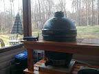
Finally, sitting back with a margarita in one hand and the prime in the other and watching my first Linkmeter controlled test smoke! Thanks to Bryan and D Peart for all the help getting this up and running!

IMG_20120317_173524.jpg
 
I'm having a problem trying to load the hex file onto the heat meter board. When I try to execute wget http://capnbry.ne ect ect... I get bad address 'capnbry.net' At this point I'm way out of my comfort zone.

Thanks
Justin
 
Originally posted by Justin:
I'm having a problem trying to load the hex file onto the heat meter board. When I try to execute wget http://capnbry.ne ect ect... I get bad address 'capnbry.net' At this point I'm way out of my comfort zone.
Is the Linksys set up as a client on your wireless network? It needs internet access to go grab the hex file. You can try `ping google.com` to see if it can get out (ctrl+C) to stop the pings.

The wiki is also behind the snapshot documentation because the file name is changing. If you have a v3.1 board you just (the separate wget command is also no longer needed)
avrupdate http://capnbry.net/linkmeter/s...heatermeter.cpp.hexA

(the file name will change once I get the build system working to auto-generate the files)
 
Good day guys..

So I received the boards (V3.2) on Saturday and immediately soldered on the components. I fired the Heatermeter up and I got the "square blocks of death" on the screen. I read through all the postings and apparently this seems to be a common problem. I began troubleshooting/debugging and found no errors. I have done the following:

1) Check continuity between the shift register and the LCD & shift register and the Atmega328 and everything tested well.
2) Tested all traces onboard and everything tested well.
3) Cleaned the board from flux build up.
4) I noticed the resonator had a slight bubble so I replaced it.
5) The LED flashes 2 times very quickly (so I assume the code is properly loaded)
6) I removed the soldered wires from the LCD and press-fitted it directly onto the board.
7) Verified that the POT was correctly positioned
8) D0 - D3 are not connected.
9) There isn't a D2 to replace with a 1N4001 (possible does not pertain to Heatermeter V3.2)

I am in the process of getting the router fixed (bricked it) for the Linkmeter so I was trying to get this going as a stand-alone unit for now. I am powering up the board via the power barrel jack (12volts, 600mAh).

Any thoughts/ideas that could help me figure this out? I really appreciate you guys helping out as I am a newb at the whole electronic hobby thing. I have learned so much, but I am not to proud to ask for help when I need it, so here I am, HELP!..

Thanks!
Edwin
 
Justin,

I think your design is AWESOME! Let me know if you plan on ordering some decals of something. I'll buy some...

- Edwin

Originally posted by Justin:
Since I haven't gotten my boards yet I was toying around with maybe doing a paint job on the router case. I kinda felt like it needed a logo so I came up with a little something. Just looking for some opinions. Maybe some opinions on how I should paint it.

http://www.flickr.com/photos/77997763@N06/6983870841/

Justin
 
Originally posted by Edwin Gonzalez:
So I received the boards (V3.2) on Saturday and immediately soldered on the components. I fired the Heatermeter up and I got the "square blocks of death" on the screen. I read through all the postings and apparently this seems to be a common problem. I began troubleshooting/debugging and found no errors. I have done the following:
Oh noeeees! This was what v3.2 was supposed to be all about: not having those.

-- Which hex file did you flash, or did you build your own
-- Also I assume your shift register is a 74HC595N (not 74LS164) right? I would think that would be obvious though, as they have different pin counts.
-- Have you tried adjusting the contrast pot? All the way in one direction should make all the boxes go away. That also checks the orientation of the LCD (if it is flipped around it wouldn't do anything)
-- EDIT: Also check the orientation of the 74NC595N, it should have the notch facing the left (with the LCD header toward you)
 
i finally got all my parts to build 3.1 linkmeter. I went to flash the hex to it and I get Sync: Error, i found that i can get hmdude to be verbose:

root@OpenWrt:/tmp# /etc/init.d/lucid stop
Stopping LuCId superserver: lucid.
root@OpenWrt:/tmp# hmdude -P/dev/ttyS1 -v -v -v -v -v
hmdude: compiled on Feb 15 2012 at 15:43:06
Using port: /dev/ttyS1
Starting sync (release RESET now)...
hmdude: Send: . [0a] / [2f] r [72] e [65] b [62] o [6f] o [6f] t [74] . [0a]
hmdude: Send: 0 [30] [20]
drain><drain
hmdude: Send: 0 [30] [20]
hmdude: Recv: . [00]
hmdude: stk500_getsync(): not in sync: resp=0x00
drain><drain
Sync: ERROR
hmdude: Send: 0 [30] [20]
drain><drain
hmdude: Send: 0 [30] [20]
hmdude: ser_recv(): programmer is not responding
Sync: ERROR
hmdude: Send: 0 [30] [20]
drain><drain
hmdude: Send: 0 [30] [20]
hmdude: ser_recv(): programmer is not responding
Sync: ERROR
hmdude: Send: 0 [30] [20]
drain><drain
hmdude: Send: 0 [30] [20]
hmdude: ser_recv(): programmer is not responding
Sync: ERROR
hmdude: Send: 0 [30] [20]
drain><drain
hmdude: Send: 0 [30] [20]
hmdude: ser_recv(): programmer is not responding
Sync: ERROR


I can get it to respond with hmdude: stk500_getsync(): not in sync: resp=0x00 when I press the reset button.

Any ideas? I bought a atmega chip from sparkfun with a bootloader on it.

Please help!
 
Originally posted by Ben Lawson:
i finally got all my parts to build 3.1 linkmeter. I went to flash the hex to it and I get Sync: Error, i found that i can get hmdude to be verbose:

I just checked the following:
-Serial pin2(RX) has continuity with pin 2 on the atmega
-Serial pin3 (TX) goes to a 10k and 4.7 k resistor. The 4.7k resistor goes to pin3 on the atmega
-On the atmega, the voltage across pin 7&8 is 4.96v

-Trying to figure out how the reset button is supposed to read, but since I get a response out of it when i press it, i *think* its ok.

So i think I've checked:
Vcc
GND
RX
TX
to the good, please correct me if I'm wrong.

Is there anything else that would b required for the hex flashing to work?

Maybe I just got a bad chip/no bootloader from sparkfun....
 
Originally posted by Bryan Mayland:
<BLOCKQUOTE class="ip-ubbcode-quote"><div class="ip-ubbcode-quote-title">quote:</div><div class="ip-ubbcode-quote-content">Originally posted by Ben Lawson:
Any ideas? I bought a atmega chip from sparkfun with a bootloader on it.
Did you get the one with the Duemilanove bootloader or the Optiboot bootloader? Try this and see if you get anything
hmdude -b57600 -v -v -v -v

(You'll also still need to do the hold-the-RESET-button thing) </div></BLOCKQUOTE>

Here's what I get

root@OpenWrt:/tmp# hmdude -b57600 -v -v -v -v
hmdude: compiled on Feb 15 2012 at 15:43:06
Using port: /dev/ttyS1
Starting sync (release RESET now)...
hmdude: Send: . [0a] / [2f] r [72] e [65] b [62] o [6f] o [6f] t [74] . [0a]
hmdude: Send: 0 [30] [20]
hmdude: Recv: . [00]
hmdude: stk500_getsync(): not in sync: resp=0x00
Sync: ERROR
hmdude: Send: 0 [30] [20]
hmdude: ser_recv(): programmer is not responding
Sync: ERROR
hmdude: Send: 0 [30] [20]
hmdude: ser_recv(): programmer is not responding
Sync: ERROR
hmdude: Send: 0 [30] [20]
hmdude: ser_recv(): programmer is not responding
Sync: ERROR
hmdude: Send: 0 [30] [20]
hmdude: ser_recv(): programmer is not responding
Sync: ERROR


And this is the atmega I got from sparkfun, ATmega328 with Arduino Optiboot (Uno)
 
Can someone tell me what value R7 should be (resistor on pin 15 of LCD to 5V)? I don't see that it is populated in the pictures, and the board and schematic don't show a value, unless I'm missing something.
 
Originally posted by Andrew Meimann:
Can someone tell me what value R7 should be (resistor on pin 15 of LCD to 5V)? I don't see that it is populated in the pictures, and the board and schematic don't show a value, unless I'm missing something.
It is only there to populate if your LCD requires a limiting resistor on the LCD backlight. The recommended Newhaven display has the resistor built in so you can leave it unpopulated or just put a piece of wire across it.
 
Originally posted by Ben Lawson:
And this is the atmega I got from sparkfun, ATmega328 with Arduino Optiboot (Uno)
It is odd it doesn't look like it has either bootloader on it, or the serial isn't working correctly.

If you check at the ATmega while it is plugged into the serial port, you should have:
Pin 1 (RESET): 5V
Pin 2 (RX): 3.3V
Pin 3 (TX): 5V

When you hold down the reset button, pin 1 should go to 0V. If you check at the router connection, the pins should have (starting from the pin closest to you) 3.3V, 3.3V, 3.3V, (don't care), 0V.

If that all checks out then either the router's serial port isn't working, or the chip has no bootloader. You can try testing the serial port by removing the HeaterMeter board and jumpering the RX and TX pins together and opening 2 terminal connections to the router. In the first type
/etc/init.d/lucid stop
cat /dev/ttyS1

In the second type
echo TEST > /dev/ttyS1

And you should see "TEST" appear in the first terminal.
 
Status
Not open for further replies.


Back
Top