Bryan Mayland
TVWBB Hall of Fame
It is on the external schematic, connected to probe jack JP6 (FOOD3/AMB) between pins 1 and 2.Originally posted by Ben Lawson:
I'm in the process of building my 3.1 board, where does TR1 go? Cant find it for the life of me
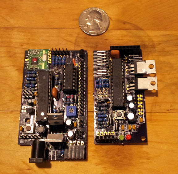
I don't have one built this way because I only have the 3 jacks, but if you look at this picture of the probe jacks you'd solder it to your 4th jack between the ground leg and the unconnected leg on the side of the jack.
What this does is connects the thermistor if no probe is plugged in, and the probe if a probe is plugged in. You can also omit the jack completely and just solder the thermistor between pin 5 of JP2 and ground.