LinkMeter v2 Homebrew BBQ Controller - Part 1


Status
Not open for further replies.
Originally posted by Kyle Christensen:
I'm not sure I'm going to even use a button on my build though, especially if we have a way to toggle the lid open mode via a mobile device.
The latest snapshot should have this working now, only the linkmeter package and the Arduino source is changed.

<pre class="ip-ubbcode-code-pre">
opkg install http://capnbry.net/linkmeter/s...meter_2_brcm47xx.ipk
/usr/bin/avrupdate http://capnbry.net/linkmeter/s.../heatermeter.cpp.hex
</pre>

There's a bunch changed under the hood to reduce the size of adding new HeaterMeter "/set" items. Notably the /set?pcX=A,B,C,R,T no longer takes 0s for values you don't want to change, just don't put a value for them. The README is updated, the wiki will be soon.
 
Ok, so this is my first time trying to upgrade via avrupdate. Getting some weirdness. First off, there's two avrupdate scripts on my Linkmeter:

root@linkmeter:/tmp# ls -la /usr/bin/avrupdate /usr/sbin/avrupdate
-rwxr-xr-x 1 root root 753 Jan 24 16:26 /usr/bin/avrupdate
-rwxr-xr-x 1 root root 815 Feb 7 18:12 /usr/sbin/avrupdate

Running the one in /usr/bin, it fails with:

root@linkmeter:/tmp# avrupdate http://capnbry.net/linkmeter/s.../heatermeter.cpp.hex
Connecting to capnbry.net (24.73.193.140:80)
hm.hex 100% |**************************************************************************************************************| 62224 0:00:00 ETA
a30b77fff264da6b3411e82dac4c2410 /tmp/hm.hex
Stopping LinkMeter OK
hmdude: compiled on Feb 7 2012 at 17:39:25
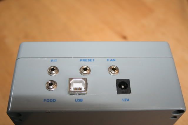
Using port: /dev/ttyS1
Loading ihex file: "/tmp/hm.hex" (22116 bytes)
Starting sync (release RESET now)...
Sync: ERROR
Sync: ERROR
Sync: ERROR
Sync: ERROR
Sync: ERROR
Update failed
Starting LinkMeter OK
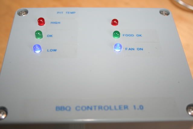
Current HeaterMeter version is 201201240

However, I'm guessing I want the newly updated one in /usr/sbin, which doesn't like urls as parameters apparently, so I download the hex:

root@linkmeter:/tmp# /usr/sbin/avrupdate heatermeter.cpp.hex
Stopping LinkMeter OK
avrdude: stk500_getsync(): not in sync: resp=0x00
avrdude: stk500_disable(): protocol error, expect=0x14, resp=0x24

avrdude done. Thank you.

Failed attempt 0
avrdude: stk500_getsync(): not in sync: resp=0x00
avrdude: stk500_disable(): protocol error, expect=0x14, resp=0x24

avrdude done. Thank you.

Failed attempt 1
Starting LinkMeter OK
Current HeaterMeter version is Unknown

Now I don't believe this chip is bootloadered with Optiboot if that makes a difference as far as hmdude is concerned. I really toasted one of my two atmegas, so the chip that's in my HM now is running whatever my Arduino shipped with last year. I do have a new chip preloaded with Optiboot on the way, but Sparkfun is being slow at processing my order...

The presets stuff in the web interface seems to work just fine now.
icon_smile.gif


Edit: I read back a ways and see that I'm having the same problem Dave did, which I'm guessing is due to the fact that I'm not running OptiBoot. Is there a way around that?

Pastebin output of hmdude sync attempt: http://pastebin.com/1KyXTB78 It does the same business, spitting out 00's then just booting into HeaterMeter.
 
I've been searching and I am only able to find mention of it in the eagle file updates. What is the ext33 on the board for?
 
Originally posted by Bryan Mayland:
<BLOCKQUOTE class="ip-ubbcode-quote"><div class="ip-ubbcode-quote-title">quote:</div><div class="ip-ubbcode-quote-content">Originally posted by James G.:
I'm at a loss here. Web page displays everything ok but just blocks on the lcd display. My display appears to be wired properly. Looking for any troubleshooting advice. Does this sound like an issue with a component wired wrong? Display wiring? Operator error?
Have you adjusted the contrast potentiometer R6? If the contrast is set too high you get one line of full blocks. </div></BLOCKQUOTE>

Yes, adjusted the pot all the way and still no characters. What are the LCD pulldowns for? I've tried with and without the resistors and no luck there either. I do have a different pot from the original heater meter build I will try. I've had this display working on the previous build and some other arduino playing. Hmmm...
 
So hooked up 12VDC and Ground to J2 the other night to test my board....
as I am turning the pot to try to get some life out of the lcd, I smell electrical.....
and noticed I let some 'Magic Smoke' out of my ATMega328 chip!
icon_mad.gif


Gonna look at the board under a magnifying glass for a solder bridge when I get a second.

Any advice? I guess I should have bought an IC socket instead of soldering the MCU direct to the board...
looks like a soldering iron and desoldering bulb and wick are in my future
icon_frown.gif
 
Originally posted by Kyle Christensen:
root@linkmeter:/tmp# ls -la /usr/bin/avrupdate /usr/sbin/avrupdate
-rwxr-xr-x 1 root root 753 Jan 24 16:26 /usr/bin/avrupdate
-rwxr-xr-x 1 root root 815 Feb 7 18:12 /usr/sbin/avrupdate

Edit: I read back a ways and see that I'm having the same problem Dave did, which I'm guessing is due to the fact that I'm not running OptiBoot. Is there a way around that?
Oops I guess there's a bit of a problem there. The proper one is /usr/bin/avrupdate, I moved it on this version because it should have never been in sbin. What you're seeing is happening because if you delete a file from the overlay filesystem in OpenWrt it actually doesn't go away because it is still in the read-only root filesystem. Not a big deal, it will go away next time you flash a TRX, and the update procedure specifies the full path too. The one you got the first time (with just `avrupdate`) was the proper one in /usr/bin

And I've never tried it but it could work flashing using the old pre-optiboot bootloader, which ran at 57600baud. Edit /usr/bin/avrupdate and change it to
hmdude -b57600 -U$HEX 2>&1
 
Originally posted by E. Fox:
I've been searching and I am only able to find mention of it in the eagle file updates. What is the ext33 on the board for?
ext33 is the jumper to enable the 3.3V regulator for powering the RFM12B. If you populate the 3.3V regulator it won't be used unless the jumper is shorted, relying on the router's 3.3V power instead. You only need to populate the 3.3V regulator and short the jumper if you're building a standalone HeaterMeter with RFM12B transceiver.
 
Originally posted by James G.:
Yes, adjusted the pot all the way and still no characters. What are the LCD pulldowns for? I've tried with and without the resistors and no luck there either. I do have a different pot from the original heater meter build I will try. I've had this display working on the previous build and some other arduino playing. Hmmm...
Ed suggested the pulldowns because he was having problems with his LCD clock line having too much capacitance and the signal wouldn't ever go low. I put them in because the LCD seemed to be the most problematic part of the design and having more potential fixes built on seemed to be a good idea at the time.

I'd suggest checking the voltage on pin 3 of the LCD as you adjust the contrast pot. It should sweep between close to 5V and 0V as you adjust it. The contrast should at least allow you to make the whole LCD black out even if all the other electrical lines aren't working.
 
Originally posted by Bryan Mayland:
And I've never tried it but it could work flashing using the old pre-optiboot bootloader, which ran at 57600baud. Edit /usr/bin/avrupdate and change it to
hmdude -b57600 -U$HEX 2>&1

Gah, why did I not think to try a diff baud rate. It worked splendidly at 57600, w/o even having to reset.
 
Originally posted by Jay Bremner:
So hooked up 12VDC and Ground to J2 the other night to test my board....
as I am turning the pot to try to get some life out of the lcd, I smell electrical.....
and noticed I let some 'Magic Smoke' out of my ATMega328 chip!
icon_mad.gif


Gonna look at the board under a magnifying glass for a solder bridge when I get a second.

Any advice? I guess I should have bought an IC socket instead of soldering the MCU direct to the board...
looks like a soldering iron and desoldering bulb and wick are in my future
icon_frown.gif

Sorry to hear your chip got fried. I also use compressed air to help desolder. It can be a little messy but it does help.

You know these chips work with smoke and mirrors. If you let the smoke out they quit working
icon_smile.gif


One thing I do prior to powering it up is to use my ohm meter to check that power/ground is not shorted. I then check power to all pins to make sure there are no shorts there. Though if you do short +5 to any of the pins it wouldn't smoke the part as the pins are all 5volt tolerant. Did you get it in backwards?

dave
 
Originally posted by Phillip Koken:
I am preparing to order the various and sundry bits that will make this project go. Is this parts list https://github.com/CapnBry/Hea...Heatermeter-hardware current for a linkmeter?
Yeah except you may have noticed the LED isn't available any more. Any 2.2V forward voltage 3mm LED rated for 5-10mA should be fine, but here's another kingbright LED that should work and should be slightly brighter than the original part. It has a slightly larger footprint 3.8mm vs 3.2mm but I think there's a mm to spare on the board. You'll have to let us know!
 
Ed suggested the pulldowns because he was having problems with his LCD clock line having too much capacitance and the signal wouldn't ever go low. I put them in because the LCD seemed to be the most problematic part of the design and having more potential fixes built on seemed to be a good idea at the time.

I'd suggest checking the voltage on pin 3 of the LCD as you adjust the contrast pot. It should sweep between close to 5V and 0V as you adjust it. The contrast should at least allow you to make the whole LCD black out even if all the other electrical lines aren't working.

When I go towards 0V I get the line of white blocks. Turning my pot I can go to 4.95V. No text.
 
I've finally gotten around to flashing the heatermeter firmware. It turns out that the Adafruit bootloader runs at 57600baud as well. So I'm up and running, web interface no longer crashes. Next I will be on to doing all of the external connections.

And I've never tried it but it could work flashing using the old pre-optiboot bootloader, which ran at 57600baud. Edit /usr/bin/avrupdate and change it to
hmdude -b57600 -U$HEX 2>&1

Edit: I forgot to mention that Laen from DorkbotPDX accidentally sent me an extra order of Linkmeter boards; I offered to send them back but he said keep them. The silk screening on them is missing labels for mostly everything. I'll put up some pictures if anyone is interested. If anyone wants these just give me a couple bucks to cover shipping (from Savannah, GA) and I'll be glad to send them out.
 
Hi to all!

After playing around with a stand-alone version of the heatermetersoftware on an arduino, I managed to get a linksys router so it's time to jump on this train
icon_smile.gif


I'd like to build up the whole thing as described in this topic. So @brandon : can you contact me at arwin2 at gmail.com ? I'd appreciate it if you send me a board...

May be a little off topic, but here are some pics of my current controllers :

IMG_8482.jpg


IMG_8481.jpg


This version doesn't use the heatermeter software, but it's pretty much based on the same idea as the one that inspired the first heatermeter project. No display, no networking, no buttons, I made some jacks with different resistors that I use as preset-plugs.

And the second version:

IMG_5416.jpg


IMG_5418.jpg


This one has an ethernet shield and to make it wireless I just took an old sitecom router and built that inside the same housing as the controller. The ethernet shield is connected to the router with a short patch-cable. The jacks are all inputs for temp probes.
Instead of using the maverick probes, I make use of the very cheap IKEA-Fantast food probes.
Limitation of those probes is their low maximum temp of 150 (or so) degrees Celsius but i found that it's quit easy to replace the internal NTC with a high temp version...

At this moment, I loaded this controller with the heatermeter software; doesn't work with the ethernetshield and sitecom router off course, but I like the way this whole linkmeter works.
So I decidet to get the linksys an jump in for this project.
 
Hey guys, awesome work so far. I was able to get a PCB from Duston and I have it all put together. Pretty Sure I have the ATMega programmed correctly, I used another Arudinuo to program it. Where I am getting hung up at is flashing the router. The router I got off ebay came loaded with dd-wrt already on it. Everything I have read says I should be able to go from dd-wrt to openwrt without any problems. I tried using the update firmware option once logged into the router to upload linkmeter-wrt54g-squashfs.bin but it returned failed to upload.

Can someone give me a step by step of how I should go about flashing this router for the first time. The Wiki is kind of vague when it comes to how to flash it. Also I am a noob at this part of the build so please dumb it down for me
icon_smile.gif


Thanks guys,
Ben
 
I make use of the very cheap IKEA-Fantast food probes.
Limitation of those probes is their low maximum temp of 150 (or so) degrees Celsius but i found that it's quit easy to replace the internal NTC with a high temp version...

Can you post more about this? Certainly cheaper than $20 per probe from Maverick...

fantast-meat-thermometer-timer__59837_PE165774_S4.jpg
 
Originally posted by James G.:
When I go towards 0V I get the line of white blocks. Turning my pot I can go to 4.95V. No text.
Ah if the contrast adjusts from nothingness to a full bar then the contrast is working. Unfortunately it sounds like you've got the "LCD doesn't work" problem that is all too common here. If you've doublechecked your connections for continuity from the shiftregister to the LCD itself, and from the ATmega to the shiftregister, you can try swapping out D2 for another 1N4001 or a 1N914/1N4148 if you have one. Other than that I can't give you much guidance. Even with an oscilloscope it is difficult to tell why the hell it isn't working.

Oh now that I have my logic analyzer I should hook that sucker up to the LCD and see if there's anything sketchy about the data showing up at the LCD! It will be tomorrow night at the earliest though.
 
Originally posted by Arwin:
May be a little off topic, but here are some pics of my current controllers :
No this is awesome! I love seeing what devices other people have built... so we can err "share" ideas. I'm with Phillip, at $7 for an IKEA probe (which comes with the unit too? what a steal!) those are great.
Measures temperatures up to 266°F/130°C.
The cord is heat-resistant up to 428°F/220°C.

Did you calculate out the steinhart coefficients? I'd be love to include them in the preset list. Also does the base unit have a beeper in it too? I bet I could use that.
 
Originally posted by Ben B.:
Can someone give me a step by step of how I should go about flashing this router for the first time. The Wiki is kind of vague when it comes to how to flash it. Also I am a noob at this part of the build so please dumb it down for me
icon_smile.gif
The reason it is vague is because I have been intentionally dodging the responsibility. The OpenWrt and DD-WRT forums are full of hundreds of people who have problems flashing the firmware, and they have a full wiki!

I don't know if you can flash either of the images from the DD-WRT gui, because I'm not sure what format they're expecting. The best bet is to use TFTP.

1) Grab the BIN snapshot
2) Get a TFTP client. If you have Windows XP, you've already got this. If not, I use the WinAgents TFTP Client Command Line utility. Put it in the same directory as your BIN file
3) Set your computer's IP address to 192.168.1.2 netmask 255.255.255.0 (gateway and dns can be blank)
4) For the most reliability connection, plug one of the target router's LAN ports into another router or hub, and then your computer into that (connecting to it via WiFi is fine too).
5) Open a command prompt and go do the directory you downloaded the BIN file and TFTP client.
6) Type `tftp -i 192.168.1.1 put linkmeter-wrt54g-squashfs.bin` but do not press enter
7) Unplug your target router, wait a couple seconds then plug it back in. Get your finger over the enter key on your computer and watch the router lights. They'll all light up as soon as you plug it in. When they all turn off (about a second or two into it) press enter.
8) The file should upload in 10 seconds, 20 at the most. If it is still sitting there after 20 seconds, hit CTRL+C and go back to #6 again.
9) If your computer sends the file successfully, in about a minute you'll see all the router lights back on again, then off. The DMZ light should start blinking fast. In another minute the Power light should come on steady. A few minutes after that, the DMZ light should go out. The router is now booted.

At this point, you can plug your computer directly into the router and get a DHCP address or set your IP to 192.168.200.x. The web interface is at 192.168.200.1.
 
Status
Not open for further replies.


Back
Top