Killed 2 Pi Zero W today :( Why?!


Louis P

New member
Second post today - that kind of day.

In an earlier thread, I explained I killed a Pi Zero W by (what I thought was) inserting it incorrectly. After being super careful, I used another Pi Zero W and also killed it! The PCB behind the CPU was extremely hot, and it smelled like magic smoke.

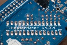
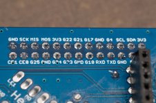
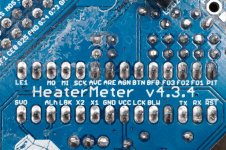
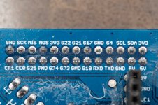
I probed the main board's Pi connector and I can't for the life of me understand what's wrong. All voltages seem ok if I compare to the schematics:

1604548587978.png

I probed 2 main boards and got the same results. Mind you, these used to work perfectly before I conformally coated the Pi - perhaps that's the issue? I'm using MG Chemicals acrylic coating - not some random brand. Worked flawlessly on my HM, so not sure if there's something particular about the Pi.

Any thoughts?

Thanks!
Louis
 
What's the deal with that UART0_TX pin, -0.13V? It actually has a negative voltage on it? Someone did have a Pi Zero W where one of the two UART pins were just completely non-functional (jumpering the two together, you'd get no data received when you transmit) but when I examined the Pi I couldn't find anything physically wrong with it. Everything else worked though in that instance, just half the serial communication wasn't working. I think it was the RX pin in that case though.
 
HI Bryan,

UART0_TX does indeed have -0.13v on it. Tracing it back to the uC itself, it also has -0.13v on the RX pin (even with its own ground).

I thought the issue might be the AVR itself, so I took it out and programmed it with the Arduino IDE bootloader, put some simple code in there (blink) and it worked fine, proving that the uC isn't the issue. While on an Arduino Uno, the same pin does not exhibit the negative voltage behaviour.

So far I've tried with 2 main boards and 3 different 328P (I use a lot for personal projects) to the same result - pin RX on the uC (and equivalent Tx on the Pi connector) all show negative voltage. I tried without a microcontroller in place and there's no voltage.

I checked all the Pi connector possible combinations, and there is no continuity except between the two 5V pins and the grounds.

I also measured voltage at the 328p level, to no great surprise (no probe attached). Below is the result:
1604621393453.png

Also below are pics of my uC and Pi header connectors soldering on 2 different boards. Please forgive the white mess - I had to remove the conformal coating, which is such a pain I kept it to the areas I had to probe.

Thanks,
Louis
 

Attachments

  • DSC_4131.jpg
    DSC_4131.jpg
    147.4 KB · Views: 28
  • DSC_4132.jpg
    DSC_4132.jpg
    109 KB · Views: 27
  • DSC_4133.jpg
    DSC_4133.jpg
    213.8 KB · Views: 26
  • DSC_4134.jpg
    DSC_4134.jpg
    144 KB · Views: 26
Soldering looks nice and clean. Nice work. Did you test the PIs standalone after conformal coating? Could be the cause, sometimes BGAs don't like getting coating underneath.
 
I have two that did exactly as you have described. One of them has a tiny burnt spot on the PCB just at the tip of the raspberry logo's right leaf.

If this is a common occurrence with a Zero W, maybe it's just not well suited for use with electrons?
 
I've had a rPi zero-w in a HM (v4.24) powered on 24/7 for well over a year with no issues. Is it possible that a component or lead on the HMv4.3 board set can come into contact with the zero-w board if it moves around or something like that?
I would be quick to point to the conformally coating except Ivan said he killed two zero-w's too, and I assume they were not coated?
I guess it is also possible that the older zero-w's like I have were different in some manner as well....
 
I believe the RX pin on the ATmega is floating normally as an input, so usually it is between 0V and 3.3V. When the ATmega is installed in a Uno board, the FTDI chip is probably driving the line high. I can't seem to find my Uno board to test with, but I believe if you pull the chip out, it will still have voltage on the Uno's RX pin, coming from the FTDI TX pin. I don't know how it can get a negative voltage but it might just be a red herring, although on a disconnected HeaterMeter here, I get 1.050V on the RX pin (coincidentally I get the same voltage on Digital 2, which isn't connected to anything on a v4.3.4 board).

That doesn't solve the mystery of the frying Zeros though. The two boards have independent 3.3V supplies and I am wondering if maybe they are so different that the signal lines are passing current? Try comparing the voltage on a 3.3V pin on a Pi (powered via USB, not from the HeaterMeter) and the 3.3V pin on the HeaterMeter and seeing if they're vastly different.
 
Soldering looks nice and clean. Nice work. Did you test the PIs standalone after conformal coating? Could be the cause, sometimes BGAs don't like getting coating underneath.
Thanks! I hadn't, and now I wish I had, as I'm scared of putting new Pis (which I won't coat) on my HM. At CDN $27 a pop, trial and error gets expensive fast!
 
I believe the RX pin on the ATmega is floating normally as an input, so usually it is between 0V and 3.3V. When the ATmega is installed in a Uno board, the FTDI chip is probably driving the line high. I can't seem to find my Uno board to test with, but I believe if you pull the chip out, it will still have voltage on the Uno's RX pin, coming from the FTDI TX pin. I don't know how it can get a negative voltage but it might just be a red herring, although on a disconnected HeaterMeter here, I get 1.050V on the RX pin (coincidentally I get the same voltage on Digital 2, which isn't connected to anything on a v4.3.4 board).
Bryan, you're correct - I tried with a Uno board without chip and both RX and TX read high.

At this point, I'm contemplating sacrificing a uC by cutting the RX pin enough so it won't touch the socket while still allowing me to probe it. As I understand it, the 328p's RX pin is connected directly to the Pi's TX pin (is that correct?), so that'll allow me to figure out if the negative voltage is coming from the board or the chip. There's no voltage on those when there's no chip, but then again, there's no chip so the test w/o 328p is not the same as cutting the pin. I'll let you know how that goes!

That doesn't solve the mystery of the frying Zeros though. The two boards have independent 3.3V supplies and I am wondering if maybe they are so different that the signal lines are passing current? Try comparing the voltage on a 3.3V pin on a Pi (powered via USB, not from the HeaterMeter) and the 3.3V pin on the HeaterMeter and seeing if they're vastly different.
Just did that and they're off by one or two mV. Not enough to pass sufficient current to kill the Pi.

Thanks!
 
Yeah the ATmega's TX pin goes directly to the RX pin on the Pi header and the ATmega RX pin goes directly to the TX pin on the Pi header. I wouldn't cut the leg off the microcontroller, really the only 3 wires that need to be connected to a pi for normal operation are TX, RX and GND, so if you have some dupont Male to Female jumper wires you can just connect what you want to check. The 5V also passes through from the HeaterMeter to the Pi to power it (or vice versa if the HeaterMeter doesn't have 12V), so either also connect that wire, or power the Pi from separate USB power and the HeaterMeter from 12V.
 
Yeah the ATmega's TX pin goes directly to the RX pin on the Pi header and the ATmega RX pin goes directly to the TX pin on the Pi header. I wouldn't cut the leg off the microcontroller, really the only 3 wires that need to be connected to a pi for normal operation are TX, RX and GND, so if you have some dupont Male to Female jumper wires you can just connect what you want to check. The 5V also passes through from the HeaterMeter to the Pi to power it (or vice versa if the HeaterMeter doesn't have 12V), so either also connect that wire, or power the Pi from separate USB power and the HeaterMeter from 12V.

Hi Brian,

I finally found the guts to plug in new Pi ZeroW in the two HMs that burned them the first time around. I went as suggested, with only TX, RX and GND to begin with (powering the Pi externally), and it went fine. I then moved on to powering the Pi with the HM and it went fine as well. Not a single problem. I'm starting to think the conformal coating on the Pis is what cause the issue to begin with, as @GSpinelli mentioned above. Not going to do it with these!

Something still bugs me though. When powering the HM with the wall plug, the RX pin on the Atmega reads between 0.5 and 1v - not negative voltage. However, when powering the HM using batteries (~13.3V DC), I do read -0.13V on the atmega RX pin. This completely baffles me, as VCCs read the same (5V is still 5V out of the OKI-78SR-5 and 3.3v is still 3.3v out of the MCP1700-33). Might that have to do with the FQU11P06TU in Q3? (I must admit I don't understand how it works in the circuit). Some other pins have different voltages as well (PD2, PD7, PB0, PB4. PD5 is normal, as LCD was at 50% voltage).

In any case, here's the voltage reading on the Atmega's pins both with the wall wart and the 13.3v DC power pack:
1607998799890.png

At this point it's just curiosity as everything is going well, but I hate not understanding how this negative voltage could be, especially since 13.3v is well within the tolerances of both the OKI-78SR-5 and FQU11P06TU.

Thanks!
Louis
 
I have to admit that I don't understand what you're seeing there either. It is very strange that the voltage can be below ground, but even weirder that it only happens on battery power and not wall power. I would even think it would be the opposite, that the wall adapter would create weird problems that would go away when on battery power since the circuit is simpler. I do not think the FQU11P06TU has anything to do with it though, that's only connected to the ATmega through its gate pin, which is driven by another MOSFET so it isn't even directly connected. I've also run boards up to 20V before without experiencing any strange serial port behavior so higher voltage isn't a problem (the limiting factor is the blower max voltage).
 
Sorry to bring up an old thread.
But my pi zero W died around 1 year ago whilst attached to the heatermeter (I've been moving and renovating my house so couldn't look into it).
My pi zero didn't have any coating on it though.
When the pi is attached to the heatermeter and powered by 12v the LCD and LEDs on the meter just flicker like it's surging. And I can't use the boards. Once removed it works fine stand alone.
Would I be better to upgrade to the 3b? Or stay with another zero and hope for the best?
I'm not able to get my hands on a multimeter because it's still in storage!
Thanks in advance
 
I wouldn't try switching to a more expensive Pi to try to fix the problem, you'll just burn more money if it burns out. There shouldn't be any flickering in the LEDs in normal operation. I'd try to figure out what is causing that first, but even with a multimeter you might have a hard time diagnosing it. The only thing I can suggest is to disconnect things (blower, damper, pi) and see if it starts behaving to get an idea where the problem lies.
 
I wouldn't try switching to a more expensive Pi to try to fix the problem, you'll just burn more money if it burns out. There shouldn't be any flickering in the LEDs in normal operation. I'd try to figure out what is causing that first, but even with a multimeter you might have a hard time diagnosing it. The only thing I can suggest is to disconnect things (blower, damper, pi) and see if it starts behaving to get an idea where the problem lies.
Hi Bryan, turns out the Pi must have died, the heater meter doesn't work when the pi is attached, the screen just flickers and nothing is useable, as soon as the pi is taken out of the equation, the flickering and dead machine turn on and works fine so it must be the pi, i noticed the pi's processor was extremely hot to the touch.
I took the pi and plugged it with its own 5v input and within a minute the processor chip was extremely hot and smelt of electric burning smoke, so i will order another pi soon.
it maybe because i had it in a hobby box rather than your case. Thingiverse is playing up here in the UK at the moment and i cant access the website.
Thanks for your help
Andy


Back
Top