RalphTrimble
TVWBB Diamond Member
I would like to wish all the good Heater Meter forum members a happy holiday season, may your celebrations be surrounded by sweet blue smoke! It's been a great year for the HM project, HMv4.2.4 is by far the best Heater Meter to date! Hat's off to Bryan for all his hard work and everyone who has contributed here, and to the administrators of TVWBB for kindly hosting the Heater Meter forum for us all.
I am proud to have been a part of this project for a couple years now and have seen the HM make great strides since I have been on board. When I built my first HM there was no damper support and overshoot was more of a problem in those days. Then came the flap damper experiment, thanks to D Peart I believe, a simple flap in a tube with a servo piggy back soldered directly to the ATMega to control it. Bryan graciously provided the code and means to control the servo damper and we were off to the races, a brand new feature and big one at that!
I was intrigued with the idea of controlling the grill by a valve rather than a fan so I jumped in and built a 3D printer, the first object I attempted to print was the flap. I chuckle as I recall my confusion watching my 3D printer make loops in thin air printing the flap without support material, "How the hell is that gonna work out?" I was thinking... Well, it's not! That was the beginning of my adventure learning to fine tune my 3D printer and create 3D models and slice them properly to build quality objects. I came up to speed pretty fast and got the flap implemented in a PVC tube first, soon thereafter I created my first damper which was a 3D printed version of a flap damper.
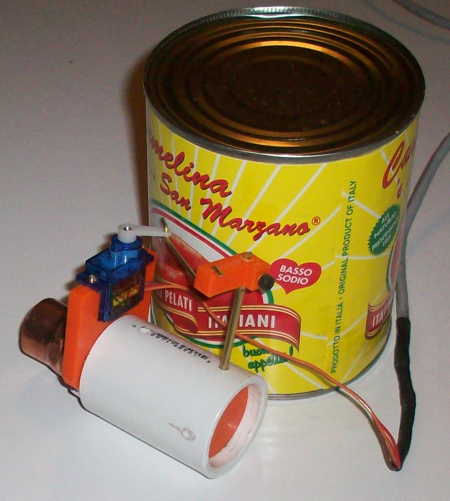
Here's a pic of the my first flap damper design:
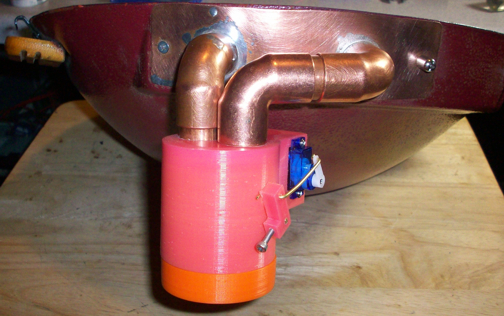
and a pic of my first all 3D printed flap damper connected to my "fauxmado" with my double barrel copper adapter freshly made and all shiny! Though this flap damper looks remarkably similar to the original roto damper it's actually quite a different beast.
I was thrilled with having the ability to close the flap and arrest overshoot, but the flap damper was essentially just an ON/OFF valve because tons of air could slip through when it is open just slightly. This immediately got me thinking, "there's gotta be a better way"... So I drew up at least three or four designs, float valves, barrel valves etc. I printed them only to end up frustrated, each being critically flawed in one way or another. Then it came to me, a rotary valve... Bingo! I made my first prototype rotary valve and the results were outstanding. That was a simple two piece barrel design, but all the principles were there, it was a quick evolution and the original Roto Damper was born!
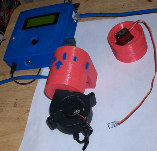
Here is a picture of the first two working prototypes of my rotary valve and the original roto damper:
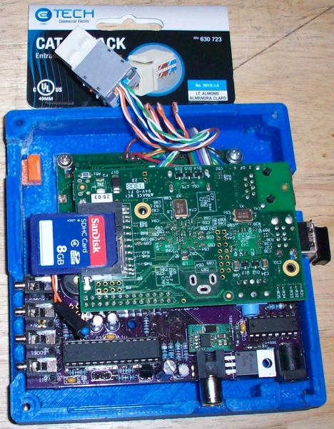
Having servo wires and an RCA cable for the blower in addition to power and probe leads connected to the HM things were becoming a bit of a rats nest for me, so I decided to use a CAT5 jack in my roto damper to clean up the mess a bit. Next I hacked my HM to add the CAT5 jack rather than having different plugs and jumpers, and immediately started experimenting with wiring options.
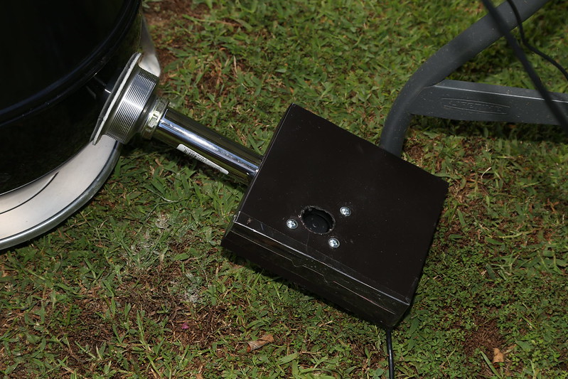
Here is a pic of my hacked HM with the CAT5 jack added:
After quite a bit of experimentation I came up with a scheme that would allow connecting not only the servo and blower through the CAT5 cable, but up to three probes as well. I was (am) thrilled with this option, while others were (and remain) sceptical of its usefulness. From my point of view I reduced the congestion at the HM down to only the CAT5 and power cables and added the ability to have the HM and Power Supply far away from the pit. WINNING! LOL I had been accustomed to putting a bowl over my HM to protect it from rain, so having the ability to move it away from the pit out of the rain was a big plus to me. So I lobbied Bryan to adopt the CAT5 jack on the HM which he eventually (perhaps reluctantly) added on HMv4.1. I had begun to experiment with running the pit on the damper alone, using the fan just to aid in the initial startup of the fire and was getting great results. I was doing this manually by removing the fan at first and had started to put together a mechanical switch to do this for me, but Bryan saved me all the trouble and added the "on at Max Only" feature for the blower to the HM config which works great for me.
After running the unit a while I began testing the limits of the cabling and resulting servo response and probe noise levels, which were at the time on the high side even when you plugged probes directly into the HM. The probes would fluctuate quite a bit and some would drop off even at room temperatures on pre HMv4.2 boards, when sent through a long CAT5 cable they were worse and the servo would occasionally erupt into spasms which in turn added even more noise to the probes. So I built up a servo booster circuit that I inserted inline that fixed up the servo real good, after a quick video demonstration of the effectiveness Bryan decided to add the servo booster to the HMv4.2 release.
Meanwhile Bryan had taken on a complete overhaul of the HM board design, focusing on eliminating noise, reorienting components, rerouting traces and adding RC filters to remove noise on the probes. The result was the HMv4.2.4 board, Bryan did an outstanding job, my probe readings and servo are now rock solid on an extremely long (~50Ft) cable. Finally all the items required for a full featured connection via CAT5 cable were in place right out of the box (except the solder pads next to the extra pins on the CAT5 jack I requested, still waiting for those") ) . Servo, blower and up to 3 probes all running through one very long CAT5 cable, rock solid... Freakin' Awesome!
) . Servo, blower and up to 3 probes all running through one very long CAT5 cable, rock solid... Freakin' Awesome!
Along with the HMv4.2 release finally came fully integrated thermocouple support, bringing the ability to control high heat cooks within the realm of possibilities for the HM. I jumped into the TC pool feet first, unfortunately to find that the TC didn't play nice with the CAT5 cable. I tried but the readings were way off, and not in a predictable way from day to day, so there was no way to compensate for it with offset settings. So I built up some hard wired TC amp circuits and started to experiment with having the TC amp in the damper so I could run the output of the amp through the CAT5 cable rather than the raw TC "signal", thinking the amp could overcome the cable issue... I was right, the TC worked great over the CAT5 cable as long as the amp was on the grill end of the cable.
I had been in communication with John Bostwick talking about the possibility of creating a small circuit board that could handle the TC and I/O in a Roto Damper, since he was already learning EAGLE board design software and I had already drawn up the circuits we decided to colaborate on the project and the "Aux Thermocouple" (RDTC) board was the result. It feels like we made a couple dozen revisions to get it right, but I'm sure its a lot less than that, in the end we got a great board put together. We are on V6.3 currently, it features the TC amp, voltage regulator circuit (to free on an extra wire for a food probe), optional REF Offset circuit I designed as well as the CAT5 jack, TC jack, two Food Probe jacks and a Servo/Blower header. We also added a Standard Pit Probe to the board which gives you the option to use the board with standard probes without installing any of the SMD components. (or gives you the option to revert to standard pit probe if your SMD soldering work on the TC amp is a total fail)
Meanwhile, high heat cooking is all the rage (at least in my back yard), I'm cooking pizza's, searing steaks and lovin' it! So I set out to redesign the RD to maximize air flow and minimize moving parts. I put together a version of what is now the RD3 built around the stock HM blower at the time, but that blower was larger and the damper was pretty darn big, so I went looking for a blower that might be a bit smaller. I found a blower that had similar specs (slightly better actually) that was smaller and I built the RD3 around that instead.... It's great blower, smaller size, better specs, wider availability, so Bryan decided it was a better choice and changed over to using it for the HM, which works out nice for the RD3 I must say. I decided to integrate the same removable control box in the orRD and RD3 so things could be somewhat universal and interchangeable, both having the hand wired or RDTC wiring options available. I also made the output on the RD3 removable, though it was not as straightforward to design this as it was with the orRD (due to the physics of 3D printing/design), I thought it was important to have the ability to interface with a wide variety of output styles to suit different rigs. Experience paid off and my initial designs were pretty spot on, just a few minor tweaks and the RD3 was alive and on the scene!
That's it in a (rather wordy) nutshell, the evolution of damper support on the HM, and the story of the creation of the RD3, my latest and greatest:
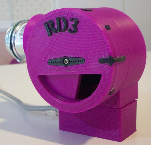
Since then I have made the RD25, which is a much larger RD3 that uses a 25CFM blower, and I have in the works an RD15 to provide something in between (I frankly believer 25CFM is way to big for anything other than a HUGE commercial pit) I also have started drawing up some designs to integrate the majority of the HM hardware right into the damper, utilizing either the new Pi Zero or the CHIP computer, I'm still not sure what direction that project is going to take at this point.
I am proud to have been a part of this project for a couple years now and have seen the HM make great strides since I have been on board. When I built my first HM there was no damper support and overshoot was more of a problem in those days. Then came the flap damper experiment, thanks to D Peart I believe, a simple flap in a tube with a servo piggy back soldered directly to the ATMega to control it. Bryan graciously provided the code and means to control the servo damper and we were off to the races, a brand new feature and big one at that!
I was intrigued with the idea of controlling the grill by a valve rather than a fan so I jumped in and built a 3D printer, the first object I attempted to print was the flap. I chuckle as I recall my confusion watching my 3D printer make loops in thin air printing the flap without support material, "How the hell is that gonna work out?" I was thinking... Well, it's not! That was the beginning of my adventure learning to fine tune my 3D printer and create 3D models and slice them properly to build quality objects. I came up to speed pretty fast and got the flap implemented in a PVC tube first, soon thereafter I created my first damper which was a 3D printed version of a flap damper.
Here's a pic of the my first flap damper design:
and a pic of my first all 3D printed flap damper connected to my "fauxmado" with my double barrel copper adapter freshly made and all shiny! Though this flap damper looks remarkably similar to the original roto damper it's actually quite a different beast.
I was thrilled with having the ability to close the flap and arrest overshoot, but the flap damper was essentially just an ON/OFF valve because tons of air could slip through when it is open just slightly. This immediately got me thinking, "there's gotta be a better way"... So I drew up at least three or four designs, float valves, barrel valves etc. I printed them only to end up frustrated, each being critically flawed in one way or another. Then it came to me, a rotary valve... Bingo! I made my first prototype rotary valve and the results were outstanding. That was a simple two piece barrel design, but all the principles were there, it was a quick evolution and the original Roto Damper was born!
Here is a picture of the first two working prototypes of my rotary valve and the original roto damper:
Having servo wires and an RCA cable for the blower in addition to power and probe leads connected to the HM things were becoming a bit of a rats nest for me, so I decided to use a CAT5 jack in my roto damper to clean up the mess a bit. Next I hacked my HM to add the CAT5 jack rather than having different plugs and jumpers, and immediately started experimenting with wiring options.
Here is a pic of my hacked HM with the CAT5 jack added:
After quite a bit of experimentation I came up with a scheme that would allow connecting not only the servo and blower through the CAT5 cable, but up to three probes as well. I was (am) thrilled with this option, while others were (and remain) sceptical of its usefulness. From my point of view I reduced the congestion at the HM down to only the CAT5 and power cables and added the ability to have the HM and Power Supply far away from the pit. WINNING! LOL I had been accustomed to putting a bowl over my HM to protect it from rain, so having the ability to move it away from the pit out of the rain was a big plus to me. So I lobbied Bryan to adopt the CAT5 jack on the HM which he eventually (perhaps reluctantly) added on HMv4.1. I had begun to experiment with running the pit on the damper alone, using the fan just to aid in the initial startup of the fire and was getting great results. I was doing this manually by removing the fan at first and had started to put together a mechanical switch to do this for me, but Bryan saved me all the trouble and added the "on at Max Only" feature for the blower to the HM config which works great for me.
After running the unit a while I began testing the limits of the cabling and resulting servo response and probe noise levels, which were at the time on the high side even when you plugged probes directly into the HM. The probes would fluctuate quite a bit and some would drop off even at room temperatures on pre HMv4.2 boards, when sent through a long CAT5 cable they were worse and the servo would occasionally erupt into spasms which in turn added even more noise to the probes. So I built up a servo booster circuit that I inserted inline that fixed up the servo real good, after a quick video demonstration of the effectiveness Bryan decided to add the servo booster to the HMv4.2 release.
Meanwhile Bryan had taken on a complete overhaul of the HM board design, focusing on eliminating noise, reorienting components, rerouting traces and adding RC filters to remove noise on the probes. The result was the HMv4.2.4 board, Bryan did an outstanding job, my probe readings and servo are now rock solid on an extremely long (~50Ft) cable. Finally all the items required for a full featured connection via CAT5 cable were in place right out of the box (except the solder pads next to the extra pins on the CAT5 jack I requested, still waiting for those
) . Servo, blower and up to 3 probes all running through one very long CAT5 cable, rock solid... Freakin' Awesome!Along with the HMv4.2 release finally came fully integrated thermocouple support, bringing the ability to control high heat cooks within the realm of possibilities for the HM. I jumped into the TC pool feet first, unfortunately to find that the TC didn't play nice with the CAT5 cable. I tried but the readings were way off, and not in a predictable way from day to day, so there was no way to compensate for it with offset settings. So I built up some hard wired TC amp circuits and started to experiment with having the TC amp in the damper so I could run the output of the amp through the CAT5 cable rather than the raw TC "signal", thinking the amp could overcome the cable issue... I was right, the TC worked great over the CAT5 cable as long as the amp was on the grill end of the cable.
I had been in communication with John Bostwick talking about the possibility of creating a small circuit board that could handle the TC and I/O in a Roto Damper, since he was already learning EAGLE board design software and I had already drawn up the circuits we decided to colaborate on the project and the "Aux Thermocouple" (RDTC) board was the result. It feels like we made a couple dozen revisions to get it right, but I'm sure its a lot less than that, in the end we got a great board put together. We are on V6.3 currently, it features the TC amp, voltage regulator circuit (to free on an extra wire for a food probe), optional REF Offset circuit I designed as well as the CAT5 jack, TC jack, two Food Probe jacks and a Servo/Blower header. We also added a Standard Pit Probe to the board which gives you the option to use the board with standard probes without installing any of the SMD components. (or gives you the option to revert to standard pit probe if your SMD soldering work on the TC amp is a total fail)
Meanwhile, high heat cooking is all the rage (at least in my back yard), I'm cooking pizza's, searing steaks and lovin' it! So I set out to redesign the RD to maximize air flow and minimize moving parts. I put together a version of what is now the RD3 built around the stock HM blower at the time, but that blower was larger and the damper was pretty darn big, so I went looking for a blower that might be a bit smaller. I found a blower that had similar specs (slightly better actually) that was smaller and I built the RD3 around that instead.... It's great blower, smaller size, better specs, wider availability, so Bryan decided it was a better choice and changed over to using it for the HM, which works out nice for the RD3 I must say. I decided to integrate the same removable control box in the orRD and RD3 so things could be somewhat universal and interchangeable, both having the hand wired or RDTC wiring options available. I also made the output on the RD3 removable, though it was not as straightforward to design this as it was with the orRD (due to the physics of 3D printing/design), I thought it was important to have the ability to interface with a wide variety of output styles to suit different rigs. Experience paid off and my initial designs were pretty spot on, just a few minor tweaks and the RD3 was alive and on the scene!
That's it in a (rather wordy) nutshell, the evolution of damper support on the HM, and the story of the creation of the RD3, my latest and greatest:
Since then I have made the RD25, which is a much larger RD3 that uses a 25CFM blower, and I have in the works an RD15 to provide something in between (I frankly believer 25CFM is way to big for anything other than a HUGE commercial pit) I also have started drawing up some designs to integrate the majority of the HM hardware right into the damper, utilizing either the new Pi Zero or the CHIP computer, I'm still not sure what direction that project is going to take at this point.
Last edited: